
Microcomputer relay protection device based on serial bus technology

A microcomputer relay protection and serial bus technology, applied in emergency protection circuit devices, electrical components, electrical digital data processing, etc., can solve the problem of poor anti-interference performance, increase the failure rate of devices, and the processor cannot distinguish input signal interference errors and other problems to achieve the effect of simplifying the connection relationship and reducing the number

Active Publication Date: 2012-05-02
NANJING INTELLIGENT APP
View PDF5 Cites 12 Cited by
  • Summary
  • Abstract
  • Description
  • Claims
  • Application Information

AI Technical Summary

Problems solved by technology

First of all, these two methods have the characteristics of relatively fixed connection functions and positions, that is, each connection on the backplane has a fixed function definition and cannot be used for other purposes, which brings flexibility.
Because there are many types of functional requirements for microcomputer relay protection devices, this method requires a large number of board types for each different model, and these boards are not common among different types of devices.
At the same time, it also makes it difficult to standardize the definition of the backplane bus signal, which increases the difficulty of function expansion and the cost of maintenance
Secondly, dedicated wiring or parallel bus has the disadvantage of poor anti-interference performance
When interference occurs, the processor cannot distinguish whether there is an interference error in the received input signal, and may even issue a wrong action command based on the wrong input. Such a situation has always been difficult to completely solve in the traditional microcomputer relay protection device. The problem
Third, there are many dedicated lines and parallel bus lines, but there is no bus management and self-test function
After the device is used for a long time, the contact is not good due to the oxidation of the contacts of the connectors, which greatly increases the failure rate of the device, and even causes misjudgment and misoperation of the device due to contact failures of the connectors.
To sum up the above reasons, the structure of the existing microcomputer relay protection device cannot meet the requirements of simple structure, stable and reliable operation for a long time, and self-checking and alarming when an internal failure occurs

Method used


Image

  • Microcomputer relay protection device based on serial bus technology
  • Microcomputer relay protection device based on serial bus technology
  • Microcomputer relay protection device based on serial bus technology

Examples


Embodiment Construction

[0012] The present invention will be further described in detail below with reference to the accompanying drawings and specific embodiments.

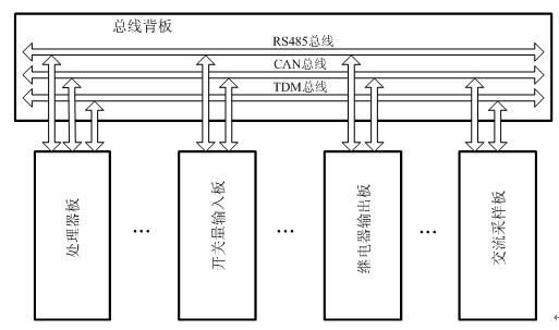
[0013] The internal structure of the present invention is as follows figure 1 As shown, it is mainly composed of a main processor plug-in board, a switch input plug-in board, a relay output plug-in board, an analog input plug-in board and a chassis backplane, and each plug-in board is connected through the backplane serial bus. The backplane serial bus includes CAN bus, RS485 bus and TDM bus. Among them, the CAN bus is mainly used to transmit the input and output and the heartbeat status information of the board card, the RS485 bus is used to transmit the board configuration information and status monitoring information, and the TDM bus is used to transmit the high-speed sampling point information of the analog channel.

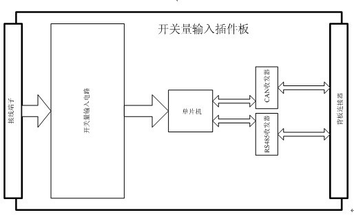
[0014] like figure 2 As shown, the switch quantity input plug-in board is mainly composed of switch quantity inpu...


PUM


Abstract

The invention discloses a microcomputer relay protection device based on a serial bus technology. On the basis of a design mode of backplanes and plug-in boards, the microcomputer relay protection device mainly comprises a master processor plug-in board, an on-off input plug-in board, a relay output plug-in board and an analog input plug-in board, wherein, the plug-in boards are connected through serial backplane buses. In the microcomputer relay protection device, a CAN (Controller Area Network) bus, an RS485 bus and a TDM (Time Division Multiplexing) bus are utilized as connecting channels of board cards. The microcomputer relay protection device has the advantages that as the serial buses are adopted instead of special connecting lines and parallel buses, the connecting lines for the backplanes are reduced, the flexibility and reliability are enhanced and the complexity of the device is lowered; and meanwhile by adopting the serial buses, a self-check function and a heartbeat return function are added for all I / O (input / output) board cards so that the device can monitor the working state in real time and an alarm can be timely sent in case of an internal fault.

Description

technical field [0001] The invention relates to a microcomputer relay protection device used in electric equipment. Background technique [0002] The microcomputer relay protection device for power equipment is an automatic device that uses microcomputer technology to analyze and calculate various state quantities of the power equipment to determine whether the power equipment is faulty, and issue an order to remove it from the power system when the fault occurs. For the sake of flexibility, the microcomputer protection device is generally composed of a plug-in structure. The processor circuit, voltage and current input conversion circuit, switch state input, relay output, etc. are placed on different circuit boards, and then connected through connectors and backplanes. Each input quantity board and the processor board are either connected by dedicated wiring or connected to the processor board bus through an interface device. The processor program reads all input quantitie...

Claims


Application Information

Patent Timeline
IPC IPC(8): H02H7/00G06F13/38
Inventor 张杭张伟
Owner NANJING INTELLIGENT APP
Learn More