Centrifugal force pendulum

A technology of centrifugal force pendulum and hydraulic force, which is applied in the field of centrifugal force pendulum, can solve the problems of vibration-absorbing mass on the limitation of vibration angle, etc., and achieve the effect of stable arrangement

CN102439329AActive Publication Date: 2012-05-02SCHAEFFLER TECH AG & CO KG
9 Cites 33 Cited by

Patent Information

Authority / Receiving Office
CN · China
Patent Type
Applications(China)
Current Assignee / Owner
Publication Date
2012-05-02

Smart Images

  • Figure 1
    Figure 1
  • Figure 2
    Figure 2
  • Figure 3
    Figure 3
Patent Text Reader

Abstract

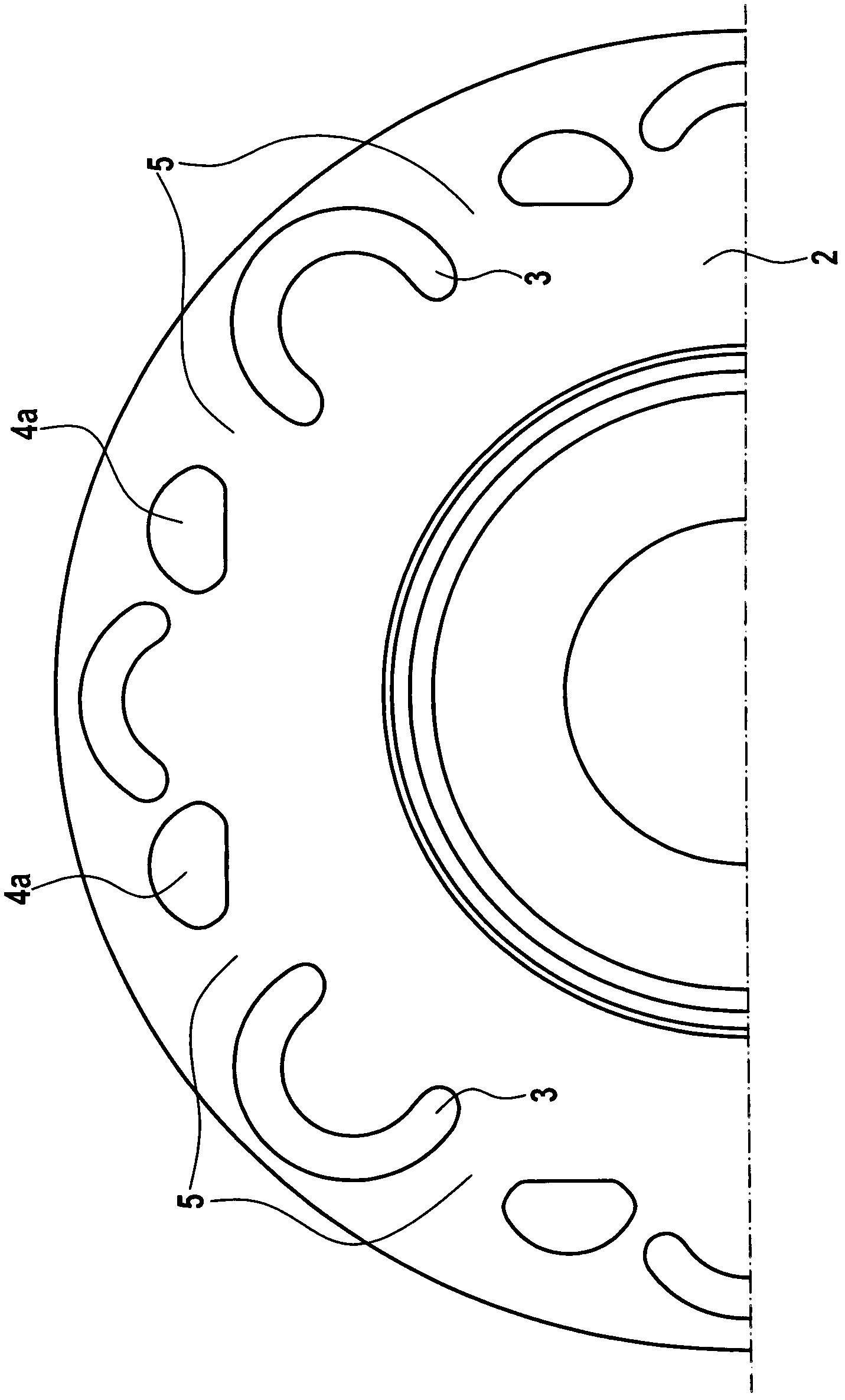
The invention relates to a centrifugal force pendulum (1), in particular for an arrangement in a drive train of a motor vehicle, comprising a pendulum flange (2) rotating about a rotational axis and a plurality of absorbers (6) arranged on said flange over the circumference thereof, wherein in each case two absorbers (6) located opposite of each other on the sides of the pendulum flange are connected to each other by way of webs (9), which each extend through an opening (3) in the pendulum flange so as to form absorber pairs (8). At the same time, cutouts (4) for receiving the absorbers are provided in the pendulum flange. In order to achieve an optimization of the available circumference of the pendulum flange for accommodating the openings and cutouts, the adjoining webs of two adjoining absorber pairs are guided through a single opening.
Need to check novelty before this filing date? Find Prior Art

Description

technical field

[0001] The invention relates to a centrifugal force pendulum with a pendulum flange and vibration-absorbing masses arranged on both sides, distributed over the circumference and deflectable relative to the pendulum flange. Background technique

[0002] The working principle of centrifugal force pendulums as torsional vibration dampers used in particular in drive trains of motor vehicles is known, for example, from DE 10 2004 011 830 A1. In this case, the damping mass is arranged so as to be deflectable on a pendulum flange, which is driven by a drive unit with torsional vibrations, such as an internal combustion engine. The damping effect of torsional vibrations occurs due to the oscillating movement of the damping mass relative to the pendulum flange due to the different rotational accelerations of the pendulum flange.

[0003] In this case, damping masses can be provided on both sides of the pendulum flange, wherein the axially opposite damping masses can ...

Examples

Embodiment Construction

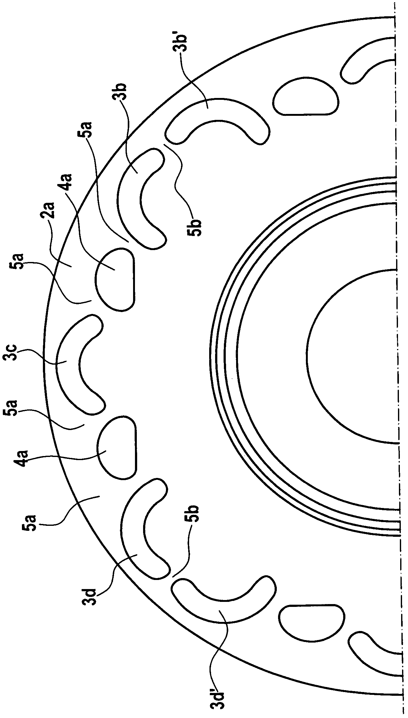
[0016] figure 1 The pendulum flange 2a of a centrifugal force pendulum according to the prior art is shown. Openings 3b, 3c, 3d are provided here for bridging elements which connect two axially spaced damping masses, each arranged next to one side face of the pendulum flange 2a, to form a damping mass pair, This is done by threading each bridge element, for example a rivet riveted to two damping masses, in an opening 3b, 3c, 3d. The shape of the openings 3b, 3c, 3d in this case is predetermined by the possible paths of the damping mass during its deflection relative to the pendulum flange 2a. The path is then predetermined by the cutouts 4a provided in the respective damping masses and the opposite cutouts, in which one rolling element rolls. Openings 3b', 3d' are perforations for bridges of adjacent pairs of vibration-absorbing masses.

[0017] For reasons of stability of the pendulum flange 2a, an intermediate region 5a must remain between the cutout 4a and the openings ...