
Auxiliary device for safe traveling of vehicles

An auxiliary device and vehicle technology, which is applied to vehicle components, transportation and packaging, elastic suspension, etc., to achieve the effects of convenient installation and layout, high test accuracy and strong adaptability

Inactive Publication Date: 2012-05-09
XIAN JINHE OPTICAL TECH
View PDF0 Cites 6 Cited by
  • Summary
  • Abstract
  • Description
  • Claims
  • Application Information

AI Technical Summary

Problems solved by technology

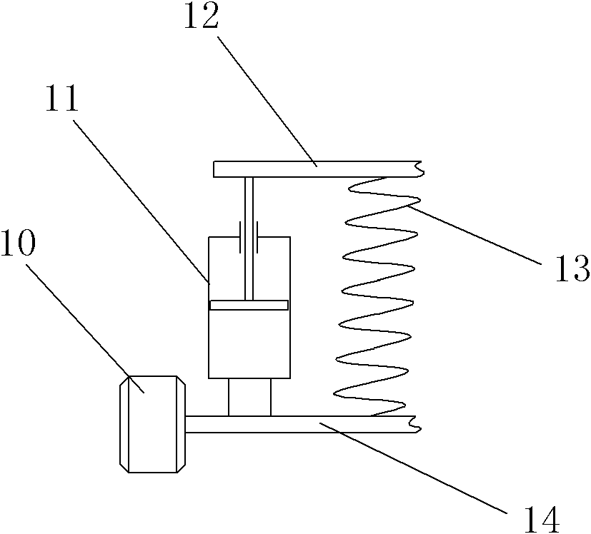
In order to reduce the volume and save space, the elastic element 13 and the shock absorber 11 are often assembled together. For example, the typical structure is that the elastic element 13 is wound and fixed on the periphery of the shock absorber 11, but its basic principle and function remain unchanged.

Method used


Image

  • Auxiliary device for safe traveling of vehicles
  • Auxiliary device for safe traveling of vehicles
  • Auxiliary device for safe traveling of vehicles

Examples


Embodiment 1

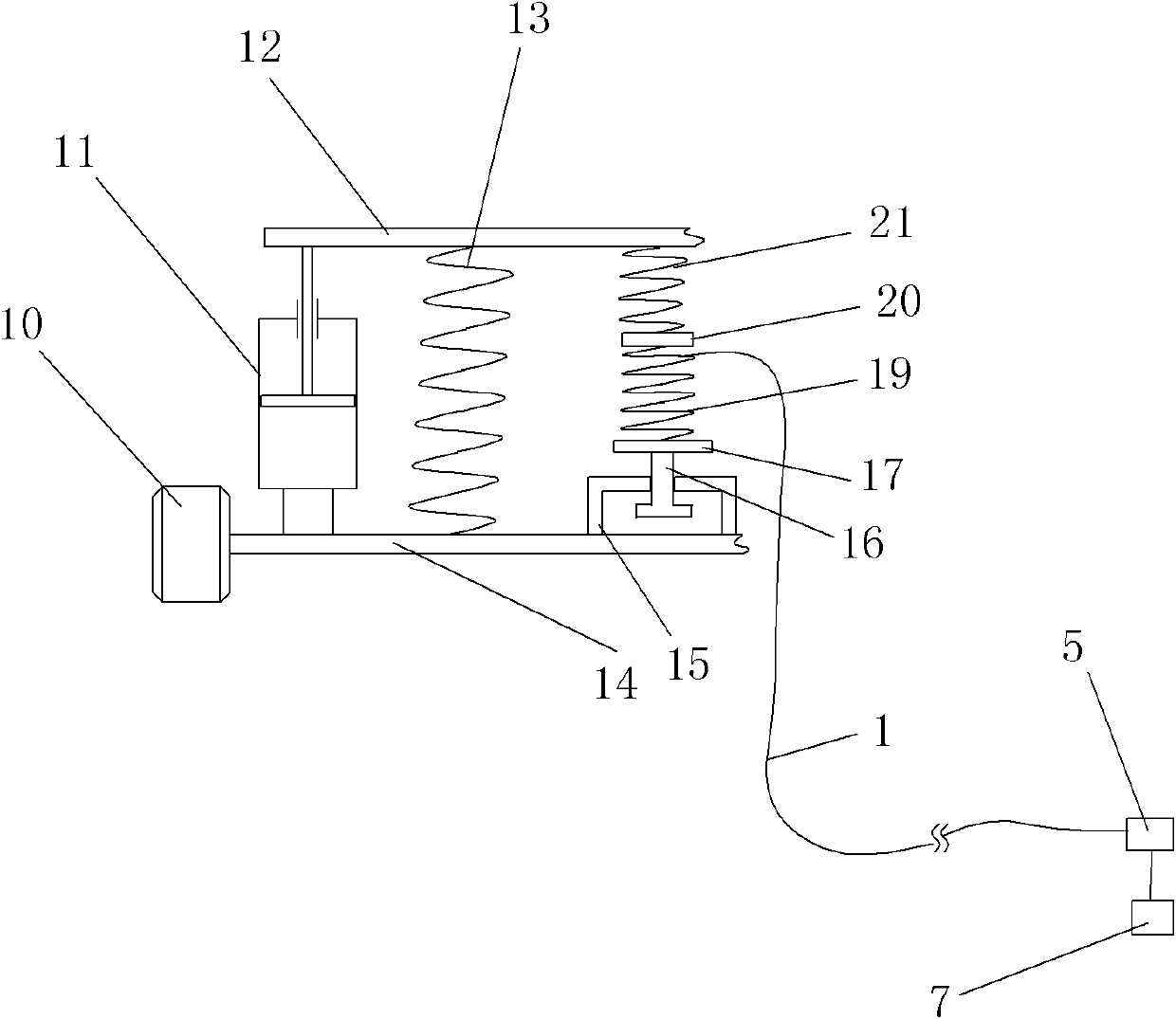
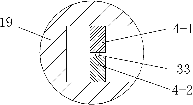
[0048] Such as figure 2 , image 3 The shown vehicle safety driving assisting device includes an optical fiber bending sensing unit arranged between the vehicle frame 12 and the axle 14 of the assisted vehicle or on the suspension device installed on the assisted vehicle, the optical fiber The bending sensing unit includes a curved test channel for the signal optical fiber 33 to pass through and a test processing unit 5 that is connected to the signal optical fiber 33 and performs synchronous testing and analysis of the optical signal power variation in the signal optical fiber 33. The processing unit 5 is connected with the central control unit ECU7 of the assisted vehicle, and the curved test channel includes a curved support and a plurality of A-side deformed teeth 4-1 and multiple A-side deformation teeth 4-1 continuously arranged on opposite sides of the curved support. A B-side deformation tooth 4-2, a plurality of A-side deformation teeth 4-1 and a plurality of B-side...

Embodiment 2

[0056] Such as Figure 4 , Figure 5 As shown, in this embodiment, the difference from Embodiment 1 is that the curved support is a spring 38, and the deformation teeth 4-1 on the A side and the deformation teeth 4-2 on the B side are correspondingly arranged adjacent to each other in the spring 38. Between the two coils of spring wires, the deformation teeth 4-1 on the A side and the deformation teeth 4-2 on the B side are alternately arranged. In this embodiment, the structures, connections and working principles of other parts are the same as those in Embodiment 1.

Embodiment 3

[0058] Such as Figure 6 , Figure 7 As shown, in this embodiment, the difference from Embodiment 1 is that the curved bracket is a bellows 40, and the deformation teeth 4-1 on the A side and the deformation teeth 4-2 on the B side are correspondingly arranged on the pipe wall of the bellows 40 On the two opposite side surfaces of the inner recess on 41, the A-side deformed teeth 4-1 and the B-side deformed teeth 4-2 are alternately arranged. In this embodiment, the structures, connections and working principles of other parts are the same as those in Embodiment 1.


PUM


Abstract

The invention discloses an auxiliary device for safe traveling of vehicles, comprising optical-fiber bending sensing units which are distributed between a frame and an axle of an assisted vehicle or distributed on a suspension device, wherein each optical-fiber bending sensing unit comprises a curve-shaped test channel and a test processing unit; the curve-shaped test channel is used for leading signal optical fibers to penetrate through; the test processing unit is connected with the signal optical fiber; the test processing unit is connected with a central control unit ECU (electronic control unit) of the assisted vehicle; the curve-shaped test channel comprises a curve-shaped bracket, a plurality of A-side deformed teeth and a plurality of B-side deformed teeth, and the plurality of A-side deformed teeth and the plurality of B-side deformed teeth are continuously distributed on the curve-shaped bracket, and are distributed in a staggered manner; and the curve-shaped channel for leading one or more signal optical fiber(s) to penetrate through is formed between the heads of the plurality of A-side deformed teeth and the plurality of B-side deformed teeth. In the auxiliary device, the structure is simple, the design is reasonable, the manufacture is convenient, the cost is low, the use mode is flexible, the sensitivity is high, the use effect is good, the practical value is high, the safety and the comfort level of the vehicle can be effectively improved and the application prospect on the market is wide.

Description

technical field [0001] The invention belongs to the technical field of vehicle driving safety status monitoring, and in particular relates to a vehicle safety driving auxiliary device. Background technique [0002] With the development of the economy, more and more families own cars, and the number of cars is also increasing rapidly. As the relationship between cars and people's life and production is getting closer, the requirements for the safety performance of vehicles are also increasing. Therefore, the safety system of the car is also constantly developing. Car safety systems are roughly divided into two categories: passive safety systems and active safety systems. The former mainly includes: impact energy-absorbing car body, safety airbag, seat belt and other devices, which are mainly used to avoid or reduce the damage to the human body after accidents; and with the development of modern car technology, sensors and modern optoelectronic technology, There are more and...

Claims


Application Information

Patent Timeline
Patent Type & Authority Applications(China)
IPC IPC(8): B60G23/00B60G17/015
Inventor 杜兵
Owner XIAN JINHE OPTICAL TECH
Learn More