

Landslide monitoring system
A monitoring system and inclinometer technology, applied in measurement devices, instruments, optical devices, etc., can solve the problem of not solving the problem of effective protection of the sensing fiber sensitivity of the sensing fiber, not fully excavating and releasing the huge potential of fiber sensing, It is difficult to meet the long-term real-time monitoring requirements of landslides and other problems, so as to achieve the effect of promoting use, flexible use, and reducing labor intensity and danger
- Summary
- Abstract
- Description
- Claims
- Application Information
AI Technical Summary
Problems solved by technology
Method used
Image

Examples
Embodiment 1
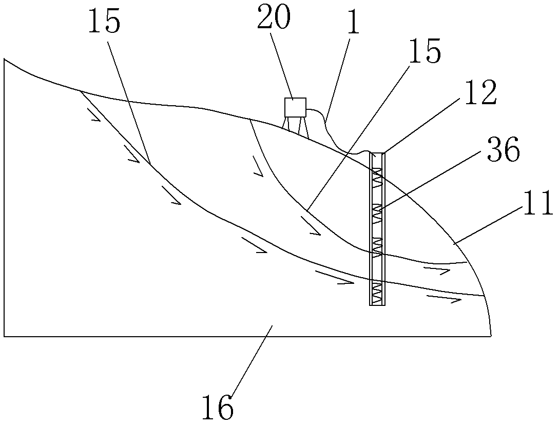
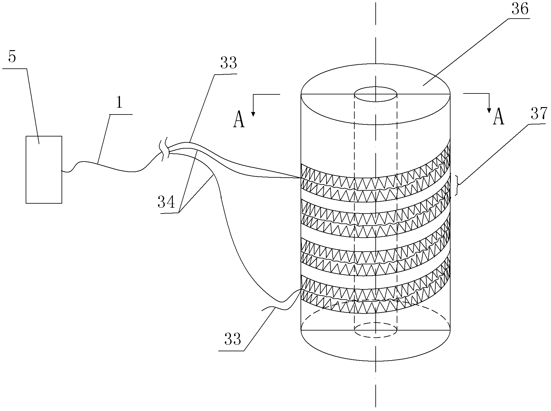
[0044] Such as figure 1 , figure 2 , image 3 , Figure 4A landslide monitoring system shown includes an inclinometer tube 12 inserted into the landslide, the inclinometer tube 12 passes through the potential sliding surface 15 of the landslide and extends into the borehole below the surface of the bedrock mass 16, the inclinometer A curved test channel for the signal optical fiber to pass through is continuously arranged in the tube 12. The curved test channel includes a cylinder 36 and a plurality of A-side deformation teeth 4 continuously arranged on the upper and lower opposite sides of the cylinder 36. -1 and a plurality of B-side deformed teeth 4-2, a plurality of A-side deformed teeth 4-1 and a plurality of B-side deformed teeth 4-2 are arranged in a staggered manner, and the heads of the two are formed for one or more The curved channel through which the signal fiber passes, the A-side deformation tooth 4-1 and the B-side deformation tooth 4-2 are correspondingly a...
Embodiment 2
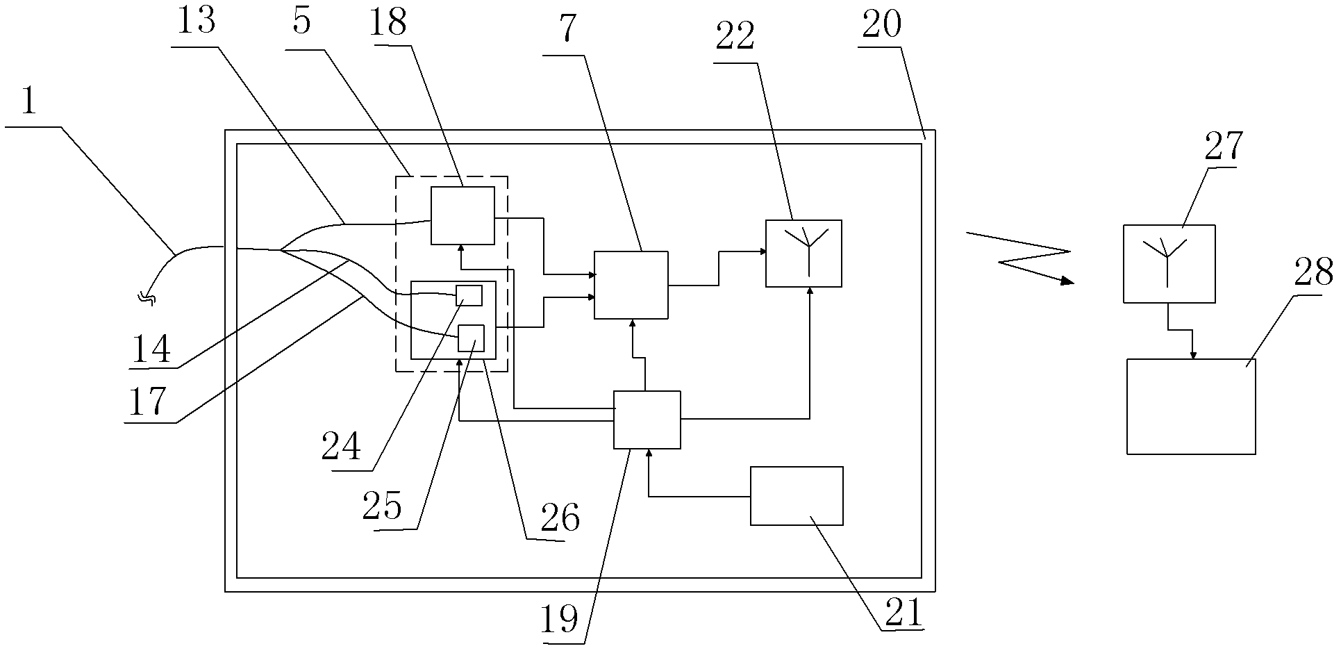
[0054] Such as Figure 5 , Figure 6 As shown, in this embodiment, the difference from Embodiment 1 is that a light reflection device 1 30 is arranged at the end of the signal fiber 2 34, and the light source-optical power meter 26 includes a 1×2 optical splitter 23, The third transmission fiber 17 is connected to the input end of the 1×2 optical splitter 23 , and the output end of the 1×2 optical splitter 23 is respectively connected to the light source 24 and the optical power meter 25 . The process is: the optical signal sent by the light source 24 enters the signal optical fiber 2 34 through the 1×2 optical splitter 23, the transmission optical fiber 3 17, and the optical cable 1, and is returned by the optical reflection device 1 30 at the end of the signal optical fiber 2 34, and Enter the optical power meter 25 through the optical cable 1, the transmission optical fiber 3 17, and the 1×2 optical splitter 23 to complete the test. In the whole process, the optical signal...
Embodiment 3
[0056] Such as Figure 7 As shown, in this embodiment, the difference from Embodiment 2 is that a plurality of light reflection devices 2 38 are arranged on the signal optical fiber 1 33, and the optical time domain reflectometer 18 can detect each light reflection device 2 38 , and calculate the difference in the reflected light power of two adjacent light reflecting devices 2 38 to obtain the bending situation between the positions of the two light reflecting devices 2 38, thereby obtaining the position and displacement of the deep part of the landslide. In this embodiment, the structures, connections and working principles of the remaining parts are the same as those in Embodiment 2.
PUM
 Abstract
Description
Claims
Application Information