Method of recording identifier and set of photomasks

a technology of photomasks and identification plates, which is applied in the direction of instruments, photo-taking processes, and semiconductor/solid-state device details, etc., can solve the problems of inconvenient deburring processing, inconvenient deburring processing, and contamination problems in many cases

Inactive Publication Date: 2005-05-24
SUMITOMO SPECIAL METAL CO LTD
View PDF18 Cites 11 Cited by
  • Summary
  • Abstract
  • Description
  • Claims
  • Application Information

AI Technical Summary

Benefits of technology

[0017]In order to overcome the problems described above, preferred embodiments of the present invention provide a method of recording various types of identifiers on a number of plate-type members by using a much smaller number of photomasks as compared to conventional methods.
[0018]Preferred embodiments of the present invention also provide a novel exposure process that is effectively applicable for use in the identifier recording method and further provide a set of photomasks for the exposure process.

Problems solved by technology

Firstly, the portion of the sintered material that has been scattered around as a result of the exposure to the laser beam is likely adsorbed or deposited as dust onto the inscribed characters, thus causing a contamination problem in many cases.
Secondly, the edges of the inscribed characters are often burred through the exposure to the laser beam. Thus, a deburring processing step needs to be carried out.
The conventional photolithographic process described above is far from being cost effective for the following reasons.
However, photomasks are normally expensive.
For that reason, as the number of photomasks needed increases, the overall processing cost of this photolithographic process increases by leaps and bounds, thus constituting a great obstacle to desired cost reduction.

Method used


Image

  • Method of recording identifier and set of photomasks
  • Method of recording identifier and set of photomasks
  • Method of recording identifier and set of photomasks

Examples


Embodiment Construction

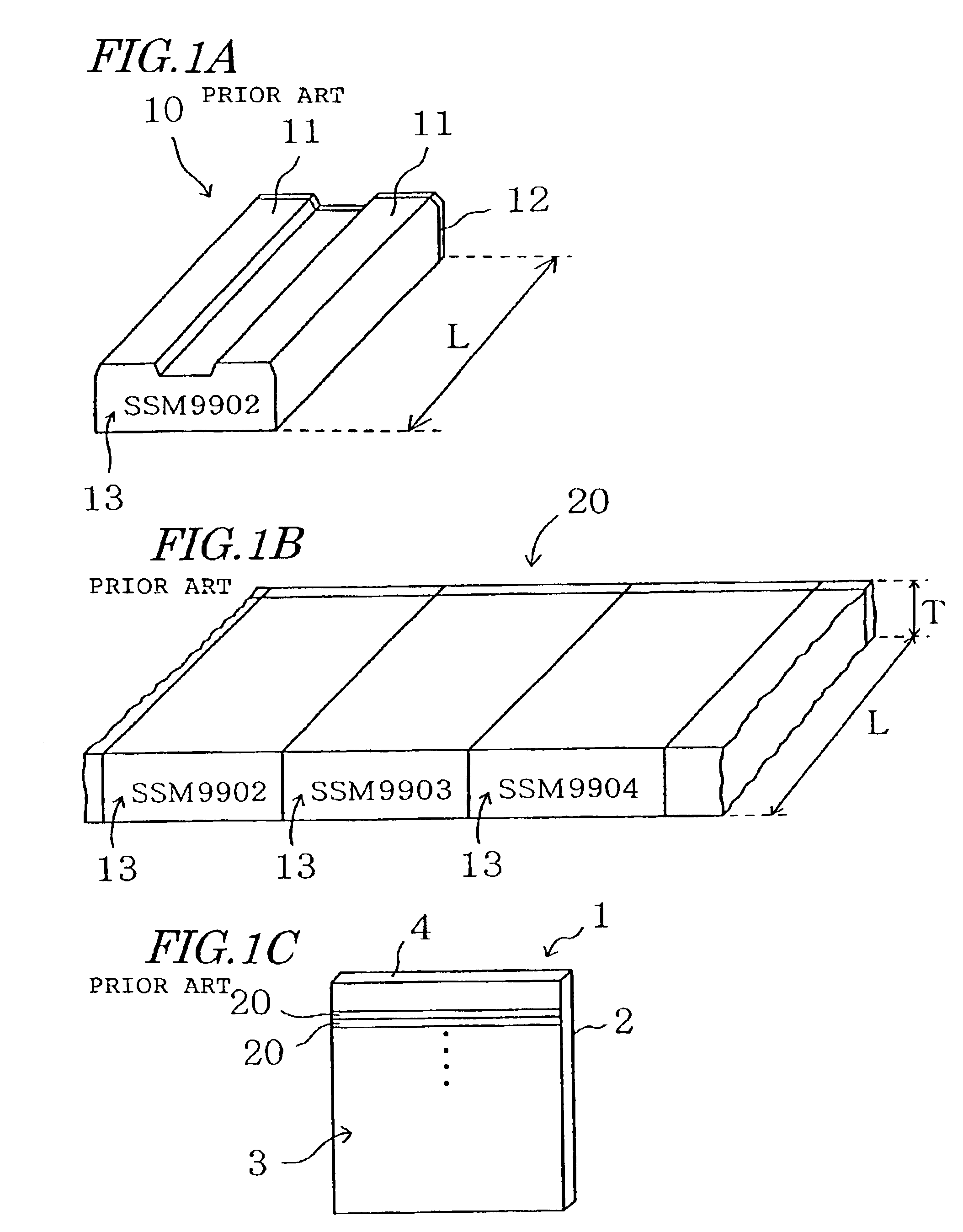
[0074]Hereinafter, a first specific preferred embodiment of the present invention will be described with reference to the accompanying drawings. In the first preferred embodiment, mutually different identifiers are recorded on multiple ceramic wafers.

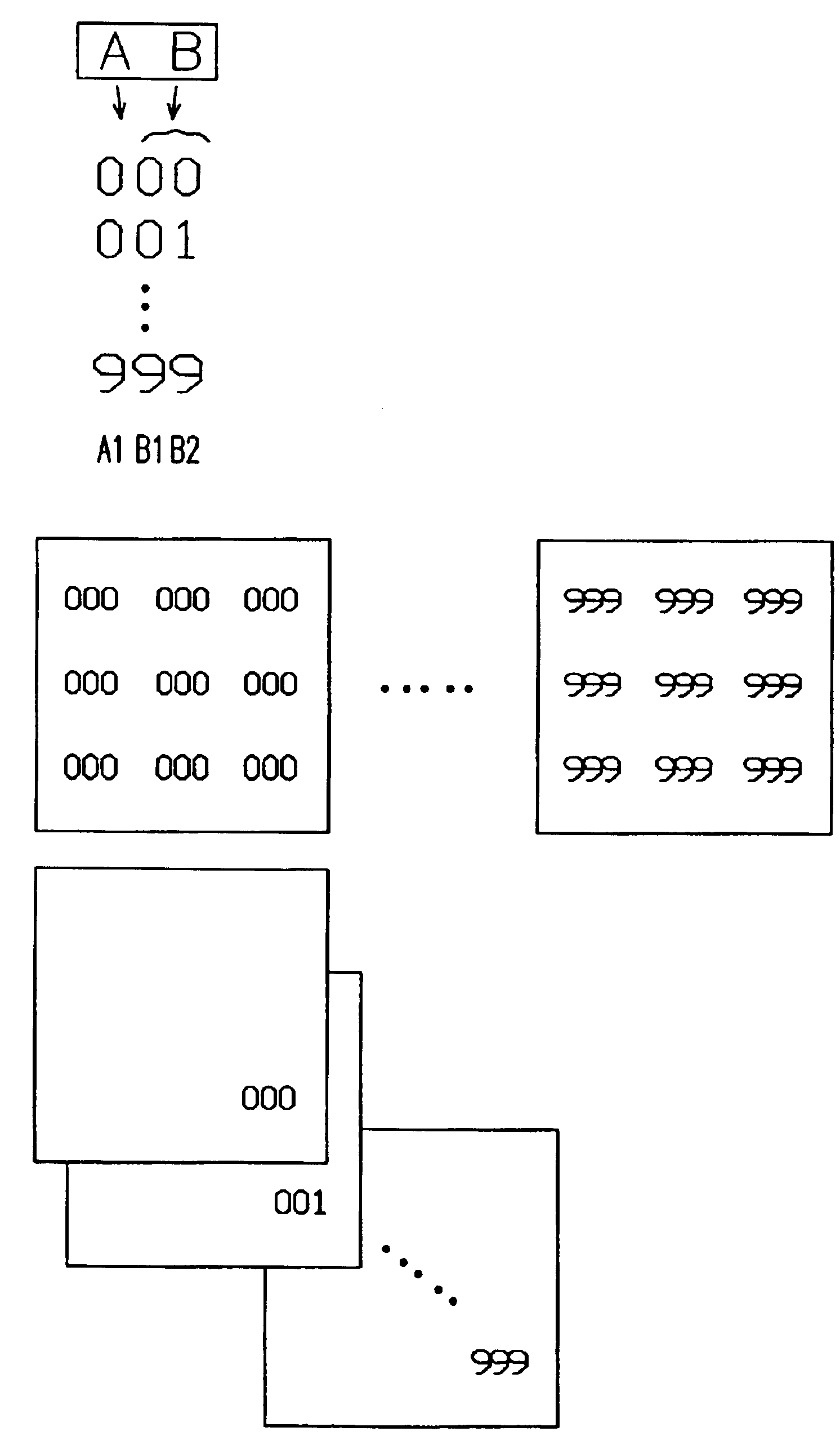
[0075]In this preferred embodiment, the identifier to be recorded on each of the wafers is represented by a group of character strings including a character string A including a number z1 of characters and a character string B including a number z2 of characters, where z1 and z2 are both natural numbers. In the following illustrative preferred embodiment, the character string A is supposed to be a one-digit character string consisting of just one character A1 and the character string B is supposed to be a two-digit character string including two characters B1 and B2 as shown in FIG. 3A for the sake of simplicity. Also, each of these characters A1, B1 and B2 is preferably one of the ten Arabic numerals of 0 through 9. That is to say, 1,0...


PUM

PropertyMeasurementUnit
thicknessaaaaaaaaaa
thicknessaaaaaaaaaa
energyaaaaaaaaaa

Abstract

A method of recording identifiers, each including a group of character strings A and B including z1, and z2 characters, respectively, on plate members involves the use of a photomask of a first type and at least one photomask of a second type. The photomask of the first type has an opaque pattern defining the character string A. The photomask of the second type has an opaque pattern defining at least one of the characters of the character string B. The method further includes the steps of forming a photoresist layer on one of the plate members, selectively exposing the photoresist layer to a radiation through the photomask of the first type to form a latent image of the character string A in the photoresist layer, and forming a latent image of the character of the character string B in the photoresist layer through the photomask of the second type.

Description

BACKGROUND OF THE INVENTION[0001]1. Field of the Invention[0002]The present invention relates to a method of recording an identifier (i.e., an ID or an ID mark) on a plate member and a set of photomasks for use in such a method. Preferred embodiments of the present invention are effectively applicable for use to inscribe an identifier not only on a ceramic wafer for a magnetic head, for example, but also on a semiconductor wafer or any other plate-type member.[0003]2. Description of the Related Art[0004]Recently, a thin-film magnetic head having any of various structures often includes a magnetic head slider for use in a hard disk drive (HDD), a tape storage and a flexible (or floppy) disk drive (FDD), for example. Examples of wafers for such a thin-film magnetic head include sintered wafers having compositions such as Al2O3—TiC, SiC and ZrO2.[0005]FIG. 1A illustrates a typical thin-film magnetic head slider 10. On its tracking side, this magnetic head slider 10 includes two side ra...

Claims


Application Information

Patent Timeline
Patent Type & Authority Patents(United States)
IPC IPC(8): G03F7/20G03F1/14G03F1/00G03F1/68G03F9/00G11B5/31G11B5/60H01L21/027H01L23/544
CPCG03F1/14G03F7/2022H01L23/544H01L2223/54473H01L2223/54426H01L2223/54453H01L2223/54406G03F1/00G03F1/42H01L2924/0002
Inventor HIROOKA, TAISUKE
Owner SUMITOMO SPECIAL METAL CO LTD
Why Eureka
Try Eureka