Smoke collecting device of iron tapping hole of rotary electric furnace

A flue gas capture and tap hole technology, which is applied to lighting and heating equipment, furnaces, and smoke removal, etc., can solve the difficulties in the design and arrangement of the exhaust hood of the tap hole of the rotary electric furnace, and the difficulty in the arrangement of the trap hood and the piping. , Increase the difficulty of collecting the hood at the tap hole and other problems, so as to achieve the effect of solving the difficulty of flue gas collection, large market value and prolonging the residence time.

Active Publication Date: 2013-07-24
BERIS ENG & RES CORP
View PDF6 Cites 0 Cited by
  • Summary
  • Abstract
  • Description
  • Claims
  • Application Information

AI Technical Summary

Problems solved by technology

[0003] The electric furnace will produce a large amount of dust-containing fume during the tapping process, especially when the iron hole is opened and blocked, the smoke generated is very concentrated, and the dust concentration is high. If it is not collected and purified in time, it will cause damage to the environment. extreme pollution
However, because the taphole flue gas has the characteristics of periodicity and large instantaneous flue gas volume, and there are many process equipment in the taphole area, it is difficult to arrange the collection fume hood and pipeline, which brings great difficulties to the collection and treatment of flue dust
[0004] In addition, the design of the taphole fume collection hood is limited by space, and the design of the fume hood is generally relatively small, especially for the design and arrangement of the taphole fume exhaust hood of the rotary electric furnace.
The rotary electric furnace will rotate at a low speed during the production process, and the taphole arranged on the furnace body will also change position with the rotation of the electric furnace, which increases the difficulty of arranging the taphole trap hood

Method used


Image

  • Smoke collecting device of iron tapping hole of rotary electric furnace
  • Smoke collecting device of iron tapping hole of rotary electric furnace
  • Smoke collecting device of iron tapping hole of rotary electric furnace

Examples


Embodiment Construction

[0022] In order to better understand the purpose, structure and function of the present invention, a kind of rotary electric furnace taphole flue gas collection device of the present invention will be further described in detail in conjunction with the accompanying drawings.

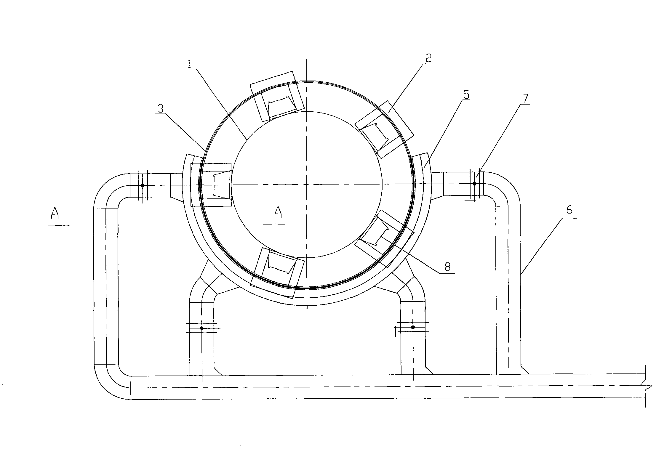
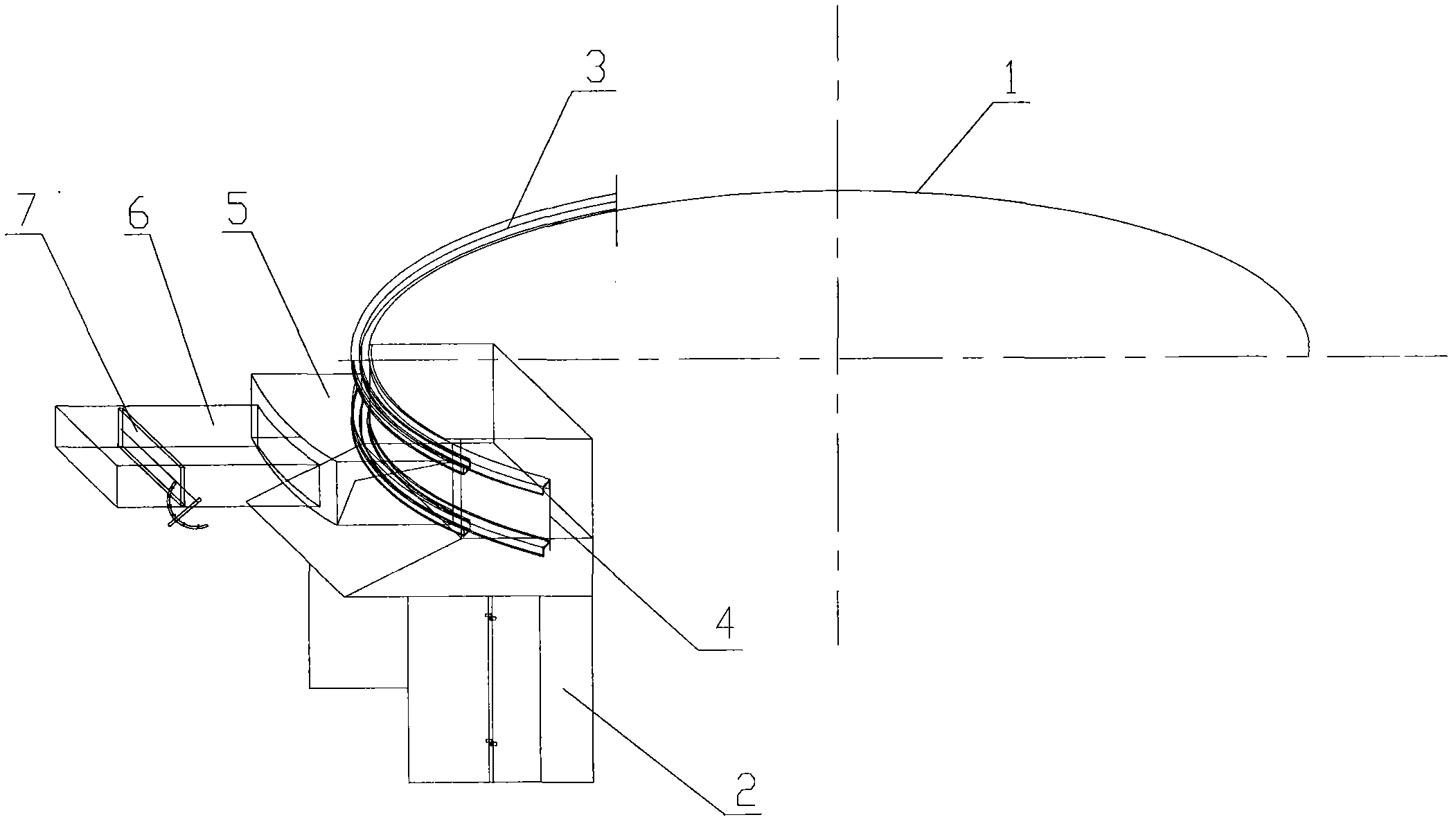
[0023] like figure 1 , 5 As shown, the rotary electric furnace of the present invention is provided with several tapholes 8, and the tapholes 8 are evenly distributed on the circumference of the furnace body of the electric furnace 1, and the molten iron smelted in the electric furnace 1 flows out from the tapholes 8, and passes through the molten iron Packet 10 is received for reprocessing. The fume collecting hood 2 in the flue gas collection device for the taphole of the rotary electric furnace of the present invention is arranged around the taphole 8 and corresponds to the taphole 8 on the 1 circle of the electric furnace one by one.

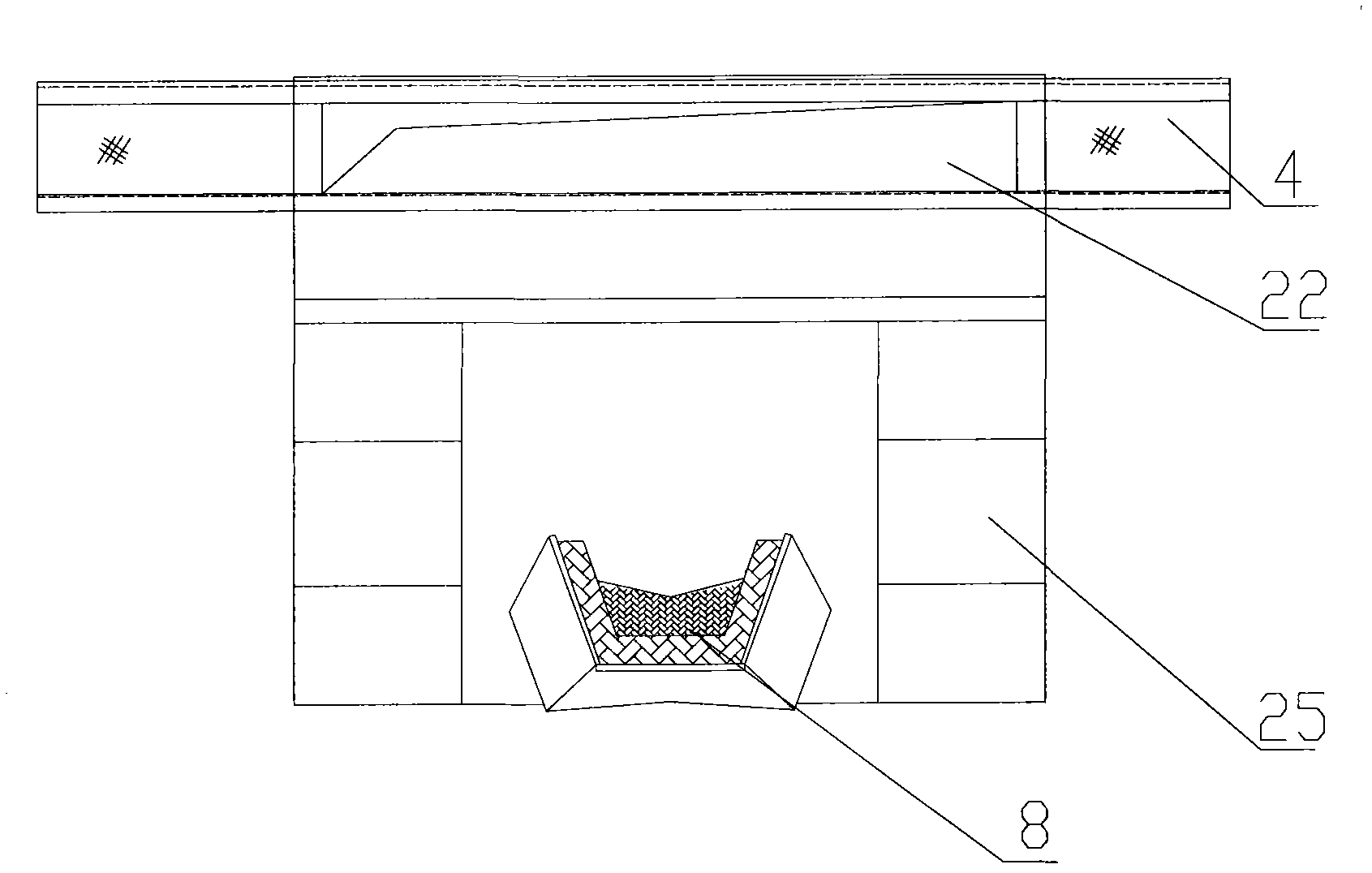
[0024] like image 3 and Figure 4 As shown, the fume collect...


PUM


Abstract

The invention discloses a smoke collecting device of an iron tapping hole of a rotary electric furnace. The smoke collecting device comprises a smoke collecting hood (2) arranged around the iron tapping hole (8), an annular chute (3) fixedly arranged outside the smoke collecting hood (2), an arc-shaped flue (5) matched on the outer side of the chute (3) in a sliding manner, and smoke discharging branch pipes (6) uniformly distributed on the flue (5). The smoke collecting hood (2) and the chute (3) rotate together with a furnace body of the electric furnace (1), and the flue (5) is fixed in a working region. The smoke collecting device of the iron tapping hole of the rotary electric furnace, provided by the invention, is used for perfectly collecting and discharging smoke generated by the rotary furnace in an iron tapping process through matching of the smoke collecting hood and a smoke discharging channel, effectively prevents smoke overflow, feasibly solves the problem of difficulty in collecting the smoke in the iron tapping hole of the rotary electric furnace, and has higher use value.

Description

technical field [0001] The invention relates to a flue gas collection device for a rotary electric furnace tapping hole, in particular to a device for collecting flue gas generated during the tapping process of a rotary electric furnace. Background technique [0002] At present, the ferroalloy smelting process is developing rapidly in China, and the electric furnace smelting process is also constantly improving and changing to meet different product requirements, and the rotary electric furnace is born. The smelting process of the electric furnace is periodic, and the iron is tapped once in each cycle, and the molten iron flows out from the taphole, and is received by the molten iron ladle for reprocessing. [0003] The electric furnace will produce a large amount of dust-containing fume during the tapping process, especially when the iron hole is opened and blocked, the smoke generated is very concentrated, and the dust concentration is high. If it is not collected and puri...

Claims


Application Information

Patent Timeline
Patent Type & Authority Patents(China)
IPC IPC(8): F27D17/00B08B15/00
Inventor 张如海杨龙军
Owner BERIS ENG & RES CORP
Why Eureka
Try Eureka