
Double-antenna network card

A dual-antenna, network card technology, applied in the field of network cards, to achieve the effect of high isolation and high efficiency

Inactive Publication Date: 2012-05-09
SHANGHAI DEMAN ELECTRONICS TECH
View PDF4 Cites 2 Cited by
  • Summary
  • Abstract
  • Description
  • Claims
  • Application Information

AI Technical Summary

Problems solved by technology

At this time, the high efficiency and same-frequency isolation between the two antennas are a big technical bottleneck.

Method used


Image

  • Double-antenna network card
  • Double-antenna network card
  • Double-antenna network card

Examples


Embodiment

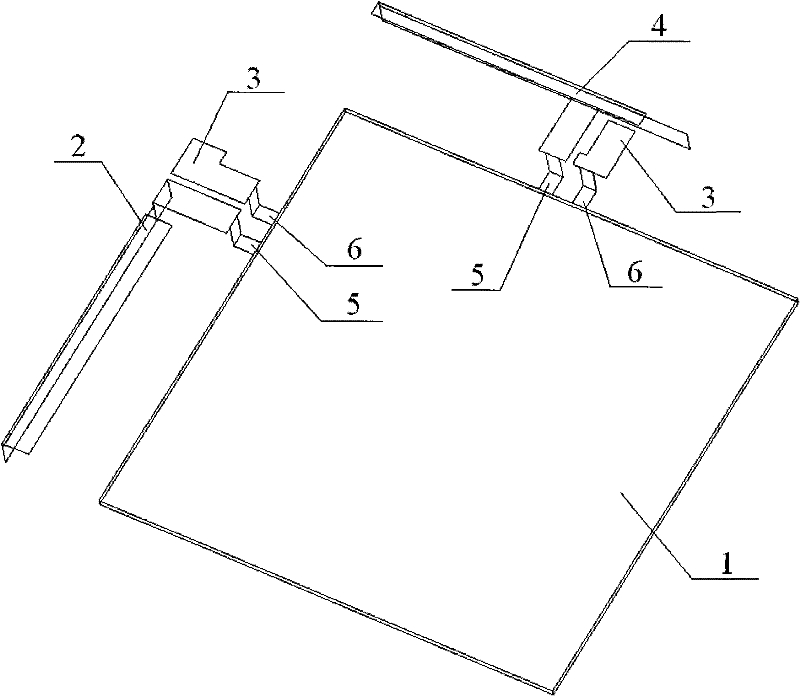
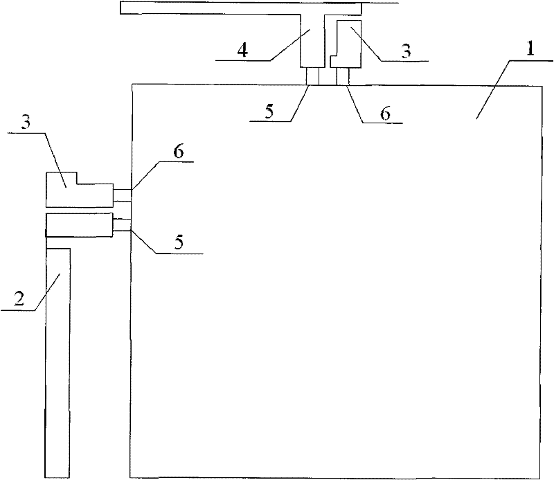
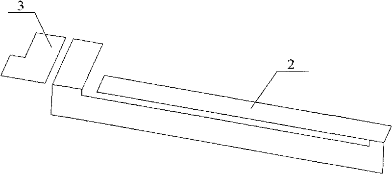
[0025] A dual-antenna network card, its structure is as follows Figure 1~2 As shown, it consists of network card 1, main antenna and auxiliary antenna. The size of the network card 1 is 82×81mm. The main antenna is set on the shorter side of the network card 1. The working frequency band is 746-960MHz and 1710-2170MHz. It is composed of the main antenna body 2 and the parasitic antenna 3. The structure of the main antenna body 2 is L-shaped, the main antenna body 2 is provided with a 14mm long hollow, connected to the network card 1 through the antenna feed point 5, and the parasitic antenna 3 is arranged on one side of the main antenna body 2, and connected to the network card 1 through the antenna ground point 6. The auxiliary antenna is located on the longer side of the network card 1, and the working frequency band is 746-960MHz and 1710-2170MHz. It is composed of the auxiliary antenna body 4 and the parasitic antenna 3. The structure of the auxiliary antenna body 4 is T-...


PUM


Abstract

The invention relates to a double-antenna network card which comprises a network card in the size of 82x81mm, a main antenna arranged on the shorter edge of the network card and an auxiliary antenna arranged on the longer edge of the network card, wherein the working frequency bands of the main antenna and the auxiliary antenna are respectively ranging from 746MHz to 960MHz and from 1710MHz to 2170MHz. Compared with the prior art, the two antennae are both high in efficiency and isolation, have wide covering frequency band and can be applied to multiple countries and regions.

Description

technical field [0001] The invention relates to a network card, in particular to a dual-antenna network card. Background technique [0002] The network card is the wireless network card, and the wireless network card is connected to the wireless wide area network, such as China Mobile TD-SCDMA, China Telecom's CDMA2000, CDMA1X, and China Unicom's WCDMA network. The role and function of the wireless network card are equivalent to the wired modem, which is what we commonly call "cat". It can use a USIM or SIM card to connect to the Internet anywhere there is wireless phone signal coverage. The role and function of the wireless network card are like a wireless modem. [0003] In the actual mobile communication system, network card pairs often work in urban buildings or other complex geographical environments, and the speed and direction of movement are arbitrary. After the transmitted signal passes through the propagation path of reflection and scattering, the signal arrivin...

Claims


Application Information

Patent Timeline
Patent Type & Authority Applications(China)
IPC IPC(8): H01Q1/24H01Q21/30
Inventor 徐墅童
Owner SHANGHAI DEMAN ELECTRONICS TECH
Learn More