Reinforced wire connection device

A splicing device and reinforced technology, applied in the direction of connecting contact materials, connections with permanent deformation, multi-core cable end parts, etc., can solve problems such as physical damage to wires, repeated temperature rises and falls, and complex splicing processes

Inactive Publication Date: 2012-05-09
江苏华厦电力成套设备有限公司
View PDF0 Cites 2 Cited by
  • Summary
  • Abstract
  • Description
  • Claims
  • Application Information

AI Technical Summary

Problems solved by technology

The disadvantages are: 1. The splicing process of the construction is relatively complicated, requiring special crimping equipment, and the installation effect is largely affected by the human factors of the operator, which is easy to cause physical damage (mechanical damage) to the wire, resulting in the occurrence of wire Strand fracture; 2. The operating life of the power line is often required to exceed 30 years. During the operation, due to the instability of the line operating load, the temperature repeatedly rises and falls, forming a thermal cycle, which increases the connection resistance, thereby increasing the line loss; at the same time The mechanical strength of the connection is reduced, which poses a threat to the safe operation of the transmission line

Method used


Image

  • Reinforced wire connection device
  • Reinforced wire connection device
  • Reinforced wire connection device

Examples


Embodiment Construction

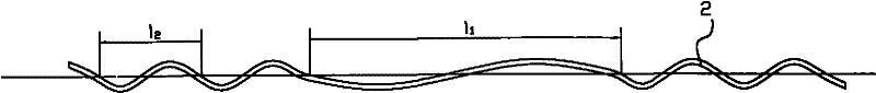
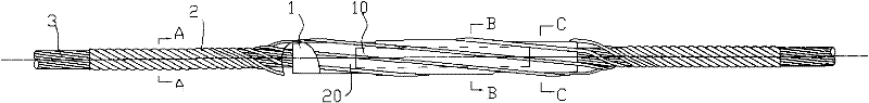
[0016] The present invention as Figure 1-8 As shown: it includes a crimping tube 1 and a reinforcing pre-twisted wire 2, the crimping tube 1 connects the wire, the reinforcing pre-twisting wire 2 is wound and wrapped around the wire and the crimping tube 1, the reinforcing The pre-twisted wire 2 is helical, and the helical direction is the same as that of the wire. The length of the reinforcing pre-twisted wire 2 is 1.5-10 times that of the crimping tube 1, and the two ends of the reinforcing pre-twisted wire 2 exceed the pressure The two parts of the connecting pipe 1 have the same length; the reinforcing pre-twisted wire 2 corresponds to the helical pitch of the crimping pipe 1 part - l 1 Consistent with the length of the crimping tube 1, the helical pitch of the two protruding parts is 2l 2 is the helical pitch-l 1 5-50% of. The connecting device needs to include 8-30 pre-twisted wires in total.

[0017] The wire of the first embodiment of the present invention is an a...


PUM


Abstract

The invention discloses a reinforced wire connection device and relates to a wire connection hardware fitting. The current-carrying capability of a connection tube is reinforced and a resistance and the loss at the connection position are also greatly reduced. Wires are abutted by a compression joint tube; a reinforcing preformed armour rod is wound and coated outside the wires and the compression joint tube; the reinforcing preformed armour rod is of a helical shape; the helical turning direction of the reinforcing preformed armour rod is the same with the turning direction of the wires; the length of the reinforcing preformed armour rod is 1.5 to 10 times of the length of the compression joint tube; the two parts at both ends of the reinforcing preformed armour rod, which exceed the compression joint tube, have equal lengths; a first helical pitch of the part of the reinforcing preformed armour rod, which corresponds to the compression joint tube, has the same length with the compression joint tube; and the lengths of second helical pitches of the two parts of the reinforcing preformed armour rod, which exceed the compression joint tube, are 5 to 50 percent of the length of the first helical pitch. In the invention, a single-layer preformed armour rod structure is adopted; and the position at the middle part of the reinforced wire connection device, which is contacted with the compression joint tube, is stranded, so that the pitch length of the reinforced wire connection device is approximate to the length of the compression joint tube and the reinforced wire connection device is convenient to install. For improving the anti-corona capability, the end of the preformed armour rod can also be subjected to special treatment, for example, the end of the preformed armour rod is made into a smooth hemisphere or duckbill shape.

Description

technical field [0001] The invention relates to a wire splicing fitting, in particular to a pre-twisted wire splicing tube reinforced splicing device. Background technique [0002] A very large number of connecting pipes are used on the electric power overhead line, and the steel core part and the aluminum layer part of the steel cored aluminum stranded wire are respectively connected in layers by hydraulic pressure or clamping technology. The disadvantages are: 1. The splicing process of the construction is relatively complicated, requiring special crimping equipment, and the installation effect is largely affected by the human factors of the operator, which is easy to cause physical damage (mechanical damage) to the wire, resulting in the occurrence of wire Strand fracture; 2. The operating life of the power line is often required to exceed 30 years. During the operation, due to the instability of the line operating load, the temperature repeatedly rises and falls, forming...

Claims


Application Information

Patent Timeline
Patent Type & Authority Applications(China)
IPC IPC(8): H01R4/20H01R4/60H01R11/11
Inventor 庄大清庄大宏郭树龙王建虎庄杰
Owner 江苏华厦电力成套设备有限公司
Why Eureka
Try Eureka