Stent

A support and coating technology, applied in the direction of stents, blood vessels, prostheses, etc., can solve the problems of unstable expansion, insufficient drug dosage, and damage to the drug coating, so as to prevent the drug from falling off and provide extremely convenient use Excellent and safe effect

Active Publication Date: 2012-05-09
TERUMO KK
View PDF12 Cites 13 Cited by
  • Summary
  • Abstract
  • Description
  • Claims
  • Application Information

AI Technical Summary

Problems solved by technology

[0008] However, the method of forming a dot-shaped coating of the drug in this way may not be sufficient in the amount of the drug, which is not ideal.
In addition, even in a stent in which the drug coating is linearly formed on parts other than the curved portion, the starting point of deformation due to expansion may coincide with the edge of the drug coating, or may be located at the edge of the drug coating in some cases. There is a starting point of deformation in the part of the stent, which may cause strain or stress concentration in the drug coating, and the drug is peeled off from the surface of the stent body, and the peeling propagates to its periphery to destroy the drug coating, resulting in a large shedding
That is, when the stent is expanded in the radial direction, the expanded size and the like are not constant, and the expanded size is different for each hand technique. Therefore, the parts other than the curved part are uniformly coated, and there is no The drug is applied in consideration of which position of the expanded curved portion becomes the starting point of the deformation. If the starting point of the deformation coincides with the edge of the drug coating, strain or stress concentration occurs in the drug coating and peeling of the drug occurs. , breakage, fall off

Method used


Image

  • Stent
  • Stent
  • Stent

Examples


Embodiment Construction

[0036] Hereinafter, embodiments of the present invention will be described in detail with reference to the drawings.

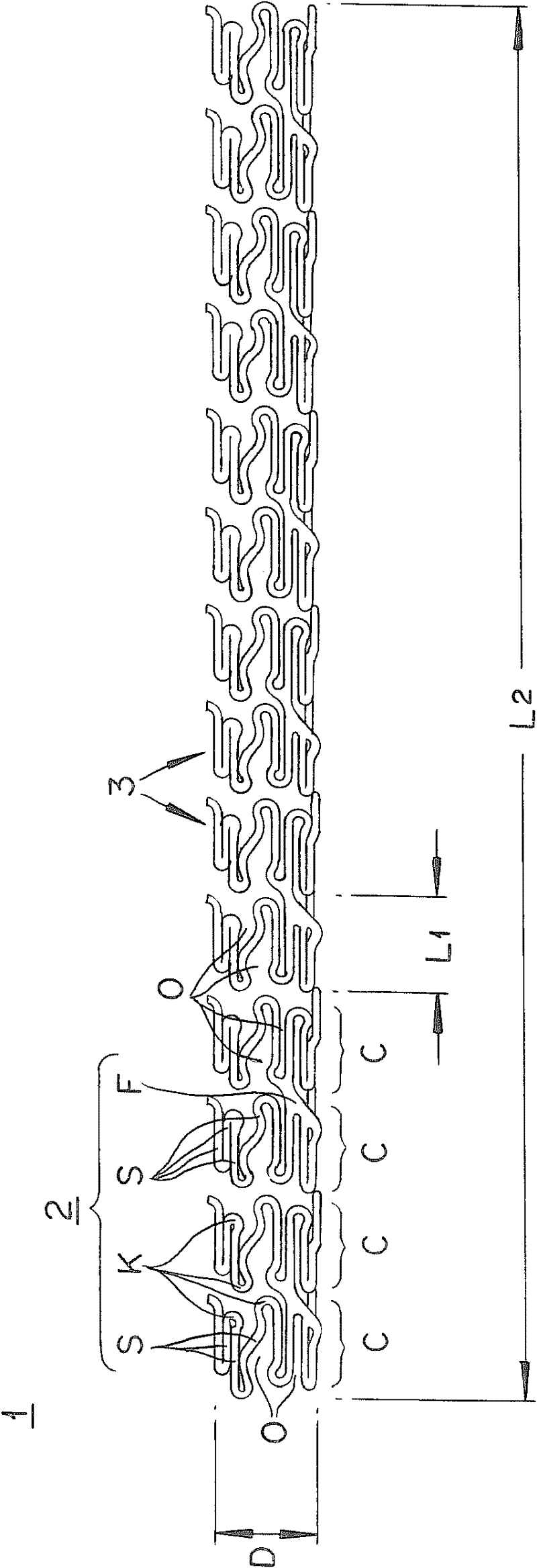
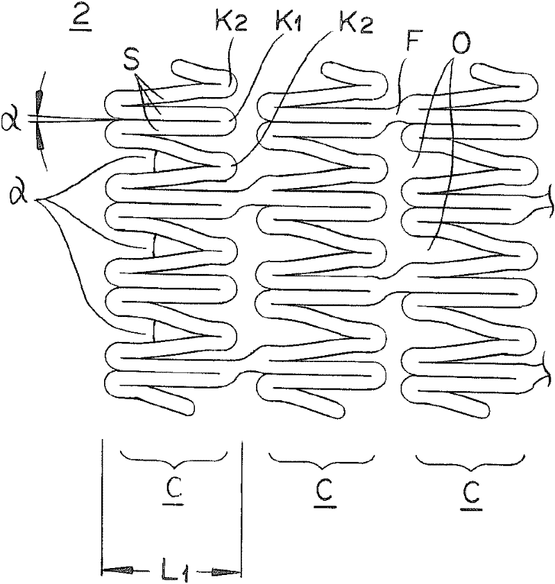
[0037] First, an overview of the brackets, such as figure 1 As shown, it includes a cylindrical stent body 2 formed by thinner supports 3, for example, and a drug coating 4 coated on the surface of the stent body 2 (refer to Image 6 ).

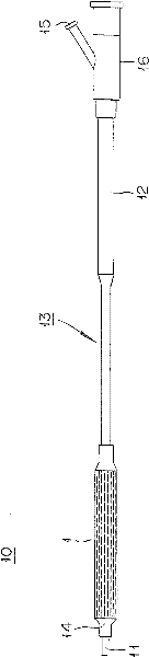
[0038] Bracket 1 uses e.g. figure 2 The stent delivery system is shown indwelling inside a blood vessel or the like. The stent delivery system 10 includes: a shaft main body 13 having a double tube structure composed of an inner tube 11 and an outer tube 12 arranged concentrically; ; a branch hub 16 having an injection port 15 for injecting fluid for dilating the balloon.

[0039]In order to indwell the stent 1 in the blood vessel using the system 10, first, the diameter of the stent 1 is reduced in such a manner that the balloon 14 in a folded state is installed on the above-mentioned system 10, and then the inner tube ...


PUM

PropertyMeasurementUnit
diameteraaaaaaaaaa
thicknessaaaaaaaaaa
lengthaaaaaaaaaa

Abstract

Provided is a stent such that there is minimal occurrence of strain or of stress concentration in a drug coated layer as a consequence of expansion and deformation of the stent in the radial direction thereof, and that as a result, there is no risk of the drug falling off. The aforementioned stent is characterized in that the thickness (B) of the drug coated layer (4) formed by coating the outer surface of a stent body (2) gradually decreases toward a bending section (K), that reduction is made to the strain and stress which occur in the drug coated layer (4) as a consequence of expansion and deformation of the stent (1), and that as a result, the drug is prevented from falling off.

Description

technical field [0001] This application is based on Japanese Patent Application No. 2009-227417 filed on September 30, 2009, and the disclosure thereof is incorporated in its entirety by reference. [0002] The present invention relates to a kind of stent which is indwelled in the stenosis or occlusion generated in the lumen of the living body to maintain the open state of the lumen, in particular to a kind of stent which is coated with medicine on the outer surface of the stent main body. DES (Drug Eluting Stent, Drug Eluting Stent) is a drug-eluting stent. Background technique [0003] A stent is a medical device used to improve narrowed or occluded parts in the lumens of blood vessels, bile ducts, trachea, esophagus, urethra, etc., and is generally a mesh-shaped cylinder formed in such a way that Use a thinner support, and form a straight or curved linear portion, U-shaped, or other curved portion continuously on the same plane, for example, in a wavy shape, and arrange ...

Claims


Application Information

Patent Timeline
Patent Type & Authority Applications(China)
IPC IPC(8): A61F2/82A61F2/915
CPCA61F2/915B05B17/00A61L2420/08A61L31/16A61F2250/0036A61F2002/91558A61F2240/001B05B13/0235A61L31/10A61F2210/0076A61L2300/00A61F2250/0067A61F2310/00149A61F2250/0037A61F2250/0041A61F2310/00017A61F2310/00035A61F2250/0031A61F2250/0029A61F2310/00389A61F2230/0069A61F2250/0026A61F2230/0006A61F2310/00023A61F2310/0097A61F2310/00059A61F2250/003A61F2310/00155C08L67/04A61F2/06A61F2/82A61F2/89A61F2002/91516A61F2002/91575A61F2002/91583A61L27/54A61L27/40A61F2002/9155
Inventor 丸山和宏斋藤昇后藤大树
Owner TERUMO KK
Why Eureka
Try Eureka