Device for particle free handling of substrates

A substrate, particle technology, applied in transportation and packaging, electrical components, semiconductor/solid-state device manufacturing, etc., can solve problems such as limiting effectiveness

Inactive Publication Date: 2012-05-09
SEMILEV
View PDF9 Cites 1 Cited by
  • Summary
  • Abstract
  • Description
  • Claims
  • Application Information

AI Technical Summary

Problems solved by technology

The effectiveness of this method is generally limited due to the turbule

Method used


Image

  • Device for particle free handling of substrates
  • Device for particle free handling of substrates
  • Device for particle free handling of substrates

Examples


Embodiment Construction

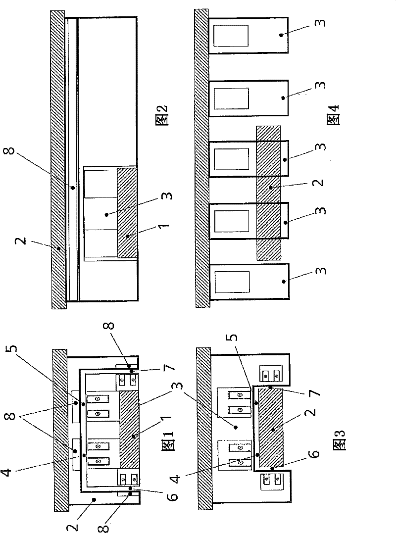
[0043] figure 1 A device for the particle-free handling of substrates (not shown) or other objects to be conveyed in a container 1 according to the invention is shown, showing a cross-sectional view transverse to the drive direction. The device consists of a fixed passive part 2 and an active part 3 that can move by magnetic force along a planned track. Since the active part is moving, it needs to be supplied with energy for the magnetic bearings 4, 5 which keep the active part floating below the passive part. The energy supply is realized by means of an electromagnetic coupling device 6 , wherein the electromagnetic coupling device 6 also supplies energy to a drive motor 7 designed as a linear induction motor. The passive part 2 is only provided with permanent magnets 8 .

[0044] figure 2 The active part 3 is shown during driving along the passive part 2 .

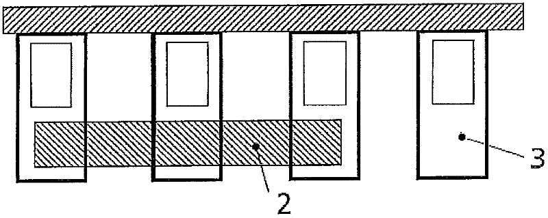
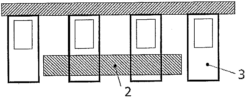
[0045] exist image 3 A stationary active part 3 with a passive part 2 being moved is shown in . The items with s...


PUM


Abstract

The invention is concerned with a device for particle free handling of substrates according of micro technology within mini environments under clean room conditions. It is a task of the invention to provide a device for handling of substrates which works friction free and thus particle free. According the invention are designed several degrees of freedom for the device whereby at least the x-, y-, z-axis and a F-direction are supported magnetic and contact free and/or guided, whereby supporting and drive of each of the axis and direction is effected contact less electromagnetic and whereby the transmission of energy for bearing and driving is effected contact less. There is designed at least one active component (3) and at least one passive component (2), whereby the movable active component (3) is guided hanging at the fixed passive component (2) by a magnet bearing (4, 5) and whereby drive motor (7) which rides with the active component (3) is coupled with an energy supply over an electromagnetic coupling.

Description

technical field [0001] The invention relates to a device for the particle-free processing of substrates, in particular for processing silicon wafers in the semiconductor industry, according to microtechnology in a microenvironment under clean room conditions. Background technique [0002] Since the application of the SMIF technology (Standard Mechanical Interface) used to process 200mm wafers in the early 1990s is silicon wafers, in semiconductor manufacturing, it is no longer handled by humans but by robots. Each manufacturing machine is therefore equipped with a so-called factory interface, EFEM (Equipment Front End Module) respectively, where said EFEM is arranged to open a transport pod - "200mm SMIF pod" - with wafers inside it and "FOUPS" (Front Opening Universal Containers) to remove the wafer and position it in the production machine. [0003] EFEM therefore constitutes the highest cleanliness standard, similar to every production machine. In the case of 200mm tech...

Claims


Application Information

Patent Timeline
IPC IPC(8): H01L21/677
CPCH01L21/67742H01L21/67766B25J9/041B25J11/0095F16C32/0406F16H49/005H01L21/67739
Inventor 马丁·安尼斯克里斯托夫·克莱森乌尔里希·奥尔登多夫托马斯·西博尔德
Owner SEMILEV
Why Eureka
Try Eureka