Fixing cutter group with positioning device

A technology for fixing cutters and positioning devices, which is applied in the direction of cutters, shearing devices, and metal processing equipment used in shearing machines, and can solve the problems of inconvenient tool setting, tool change, assembly and disassembly, low size consistency of parts, and Poor processing accuracy and other problems, to achieve the effect of simple structure, high processing accuracy, and ensure the sharpness of the blade

Inactive Publication Date: 2012-05-16
THE NORTHWEST MACHINE
View PDF0 Cites 5 Cited by
  • Summary
  • Abstract
  • Description
  • Claims
  • Application Information

AI Technical Summary

Problems solved by technology

The fixed cutter group with a positioning device used in the prior art has the following disadvantages: poor machining accuracy of parts, low

Method used


Image

  • Fixing cutter group with positioning device
  • Fixing cutter group with positioning device

Examples


Embodiment Construction

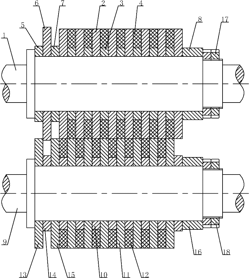
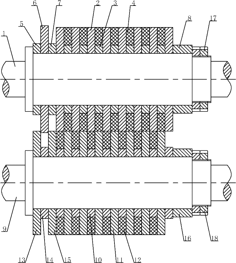
[0024] Such as figure 1 The shown fixed cutter group with a positioning device includes an upper knife part and a lower knife part, and the upper knife part includes an upper knife shaft 1 and disc knives 1 and 2 arranged in the middle of the upper knife shaft 1 at even intervals. Knife shim one 3, rubber ring one 4 is arranged on the outside of said knife shim one 3, said lower knife part includes lower knife shaft 9 and knife shim two 10 and disc knife two 11 installed in the middle of lower knife shaft 9 at even intervals, A rubber ring 2 12 is arranged on the outside of the knife shim 10, and a guide knife shim 1 5, a guide knife 6 and a positioning knife shim 7 are installed on the left part of the upper knife shaft 1, and the guide knife shim 1 5 is located on the guide knife On the left side of one 6, the positioning knife pad 7 is located on the right side of the guide knife one 6 and on the left side of the disc knife one 2, the disc knife one 2, the knife pad one 3, ...


PUM


Abstract

The invention discloses a fixed cutter group with a positioning device. The fixed cutter group comprises an upper cutter part and a lower cutter part, wherein the upper cutter part comprises an upper cutter shaft, and a cutting disc I and a cutter pad I which are arranged on the middle part of the upper cutter shaft at a uniform interval; the lower cutter part comprises a lower cutter shaft, and a cutter pad II and cutting disc II which are arranged on the middle part of the lower cutter shaft at a uniform interval; a guide cutter pad I, a guide cutter I and a positioning cutter pad are arranged on the left part of the upper cutter shaft; the guide cutter pad I is positioned on the left side of the guide cutter I; the positioning cutter pad is positioned on the right side of the guide cutter I; the cutting disc I, the cutter pad I, the guide cutter pad I, the guide cutter I and the positioning cutter pad are fixedly connected into a whole; a guide cutter II, a guide cutter pad II and a positioning cutter are arranged on the left part of the lower cutter shaft; the guide cutter II is positioned on the left side of the guide cutter pad II; the positioning cutter is positioned on the right side of the guide cutter pad; and the cutter pad II, the cutting disc II, the guide cutter II, the guide cutter pad II and the positioning cutter are fixedly connected into a whole. The fixed cutter group has a reasonable design, high processing accuracy and high processing efficiency, and is convenient to detach and use.

Description

technical field [0001] The invention relates to a cutting cutter, in particular to a fixed cutter group with a positioning device for a rolling shear. Background technique [0002] The fixed cutter group with positioning device is a necessary tool in the slitting process of the rolling shear, and is used for slitting black, non-ferrous, stainless steel and rare metal strips. The fixed cutter group with a positioning device used in the prior art has the following disadvantages: poor processing accuracy of parts, low processing efficiency, low dimensional consistency of parts, inconvenient tool setting, tool changing, assembly and disassembly, and high cost. Contents of the invention [0003] The technical problem to be solved by the present invention is to provide a fixed cutter group with a positioning device, which is simple in structure, reasonable in design, easy to assemble and disassemble, and has high processing precision and high processing efficiency. Can well mee...

Claims


Application Information

Patent Timeline
IPC IPC(8): B23D35/00
Inventor 王彦斌
Owner THE NORTHWEST MACHINE
Why Eureka
Try Eureka