
Circulating water recycling and cooling system for thermal power plant

A cooling system and circulating water technology, applied in applications, steam engine installations, fish farming, etc., can solve the problems of lack of waste heat recycling system, high cost of power generation, energy waste, etc., and achieve low temperature, simple structure and reliable operation. Effect

Inactive Publication Date: 2012-05-16
兰凯
View PDF7 Cites 1 Cited by
  • Summary
  • Abstract
  • Description
  • Claims
  • Application Information

AI Technical Summary

Problems solved by technology

[0002] The current circulating water cooling system of thermal power plants is recycled by returning to the inner cooling circuit of the generator after being cooled by the water tower. Most of the remaining heat energy is dissipated into the atmosphere through the water tower. Most of the cooling circuits are not connected with civil heat exchangers and The heat exchange device for warm water aquaculture needs to invest in the construction of a water tower with a large volume or heat dissipation area, and lacks a waste heat recovery system with an intelligent temperature control device, resulting in a certain amount of energy waste and high power generation costs.

Method used


Image

  • Circulating water recycling and cooling system for thermal power plant
  • Circulating water recycling and cooling system for thermal power plant
  • Circulating water recycling and cooling system for thermal power plant

Examples


Embodiment

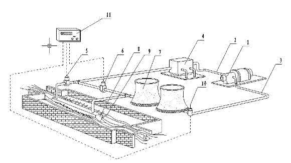
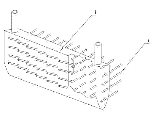
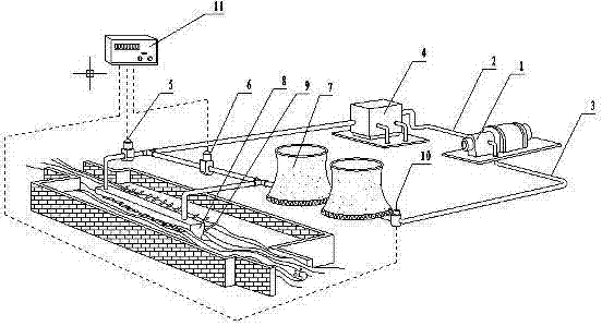
[0012] Example: a structure such as figure 1 , figure 2 As shown, the inner cooling circuit 1 of the generator, the cooling water output pipe 2, the return pipe 3, the user heat exchanger 4, the solenoid valve A5, the solenoid valve B6, the water drying tower 7, the culture pond heat exchanger 8, and the superconducting heat pipe 9 , a temperature sensor 10 and a temperature control switch 11, wherein one end of the cooling water output pipe 2 is connected to the inner cooling circuit 1 of the generator, and the other end is respectively connected to the user heat exchanger 4, the solenoid valve A5, the culture pond heat exchanger 8, Water drying tower 7, temperature sensor 10 are connected with return pipe 3, superconducting heat pipe 9 forms a whole with culture pond heat exchanger 8, and temperature control switch 11 is connected with temperature sensor 10, electromagnetic valve A5 and electromagnetic valve B6 respectively by electric line. The user heat exchanger is ...


PUM


Abstract

The invention relates to a circulating water recycling and cooling system for a thermal power plant, and belongs to the fields of energy-saving technology and special equipment manufacturing technology for a power plant. The system consists of a cooling loop in a power generator, a cooling water output pipe, a return pipe, a user heat exchanger, an electromagnetic valve A, an electromagnetic valve B, a water airing tower, a culture pond heat exchanger, a superconducting heat pipe, a temperature sensor and a temperature control switch, wherein one end of the cooling water output pipe is connected with the cooling loop in the power generator, and the other end of the cooling water output pipe is respectively connected with the user heat exchanger, the electromagnetic valve A, the culture pond heat exchanger, the water airing tower, the temperature sensor and the return pipe. When the system is in use, high-temperature cooling water flowing out from the cooling loop in the power generator is regulated and controlled by the temperature sensor and the temperature control switch, so that residual heat of the return water is released into different radiators in the closed loop, thereby ensuring the stability of water quality while outputting the residual heat; and moreover, the system has the advantages of reasonable design, simple structure and reliability in operation.

Description

technical field [0001] The invention relates to a cooling system for recycling circulating water in thermal power plants, and belongs to the technical field of energy-saving technology and special equipment manufacturing in power plants. Background technique [0002] The current circulating water cooling system of thermal power plants is recycled by returning to the inner cooling circuit of the generator after being cooled by the water tower. Most of the remaining heat energy is dissipated into the atmosphere through the water tower. Most of the cooling circuits are not connected with civil heat exchangers and The heat exchange device for warm water aquaculture needs to invest in the construction of a water tower with a large volume or heat dissipation area, and lacks a waste heat recovery system with an intelligent temperature control device, resulting in a certain amount of energy waste and high power generation costs. Contents of the invention [0003] Aiming at the def...

Claims


Application Information

Patent Timeline
IPC IPC(8): F01K27/02A01K63/06
Inventor 兰凯
Owner 兰凯
Learn More