

Heat recovery system
A heat recovery and heat technology, applied in heating systems, preheating, household heating, etc., can solve problems such as inability to obtain warm water
- Summary
- Abstract
- Description
- Claims
- Application Information
AI Technical Summary
Problems solved by technology
Method used
Image

Examples
Embodiment 1
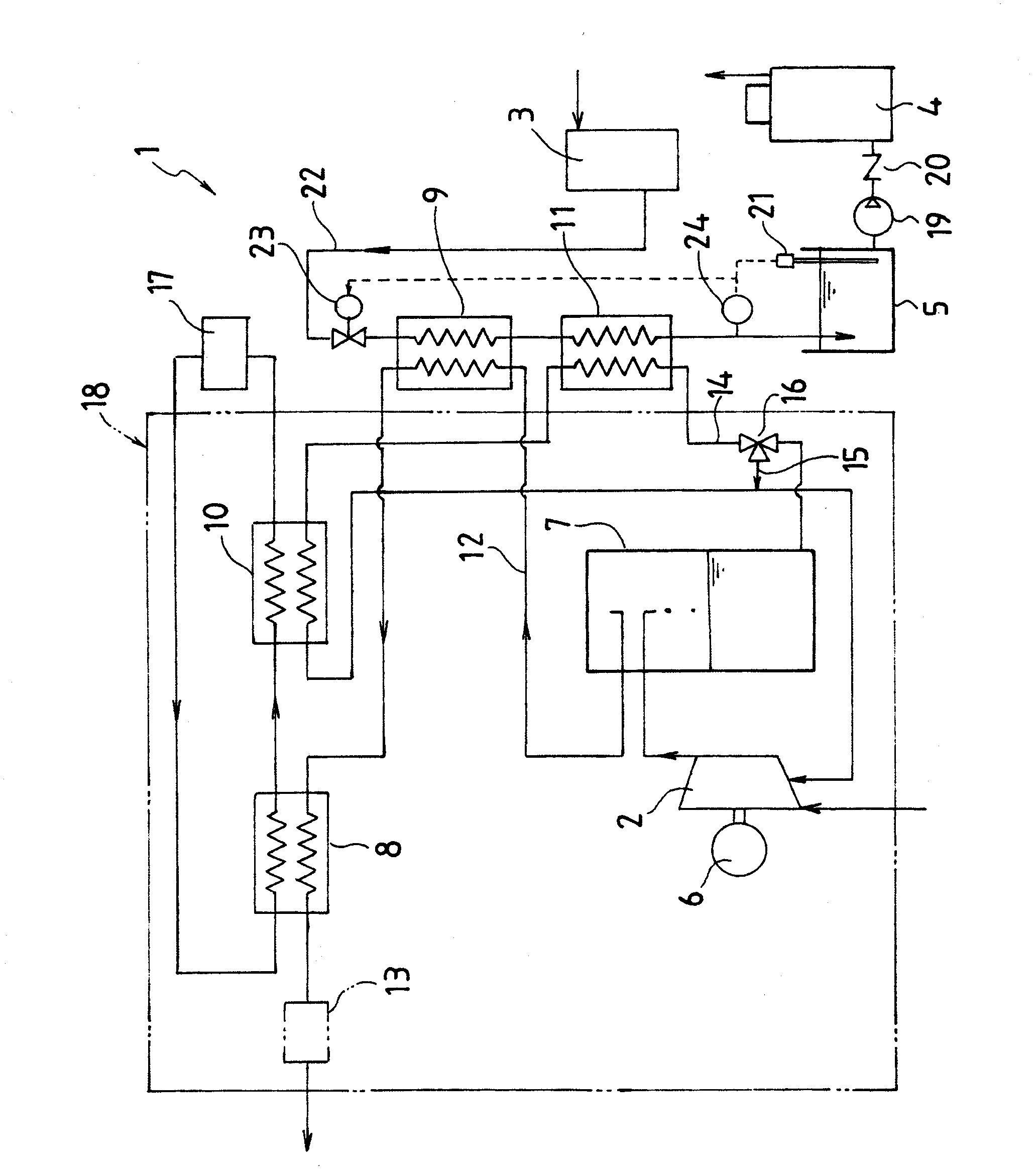
[0058] figure 1 It is a schematic diagram showing Example 1 of the heat recovery system of the present invention.
[0059] The heat recovery system 1 of this embodiment is a system for recovering compression heat from an oil-lubricated (oil-supplied) and water-cooled electric air compressor. Specifically, it is a kind of indirect heat exchange between the compressed air or lubricating oil from the compressor 2 and the water supply from the water softener 3 to the water supply tank 5 of the boiler 4, so as to realize the cooling of the compressed air or lubricating oil and the water supply tank. 5 heating systems for water supply.
[0060] The heat recovery system 1 of this embodiment mainly includes: a compressor 2 that sucks in, compresses and discharges external air, an electric motor 6 that drives the compressor 2, an oil separator 7 that separates lubricating oil from the compressed air, and realizes cooling of the compressed air. The first air cooler 8 and the second ai...
Embodiment 2
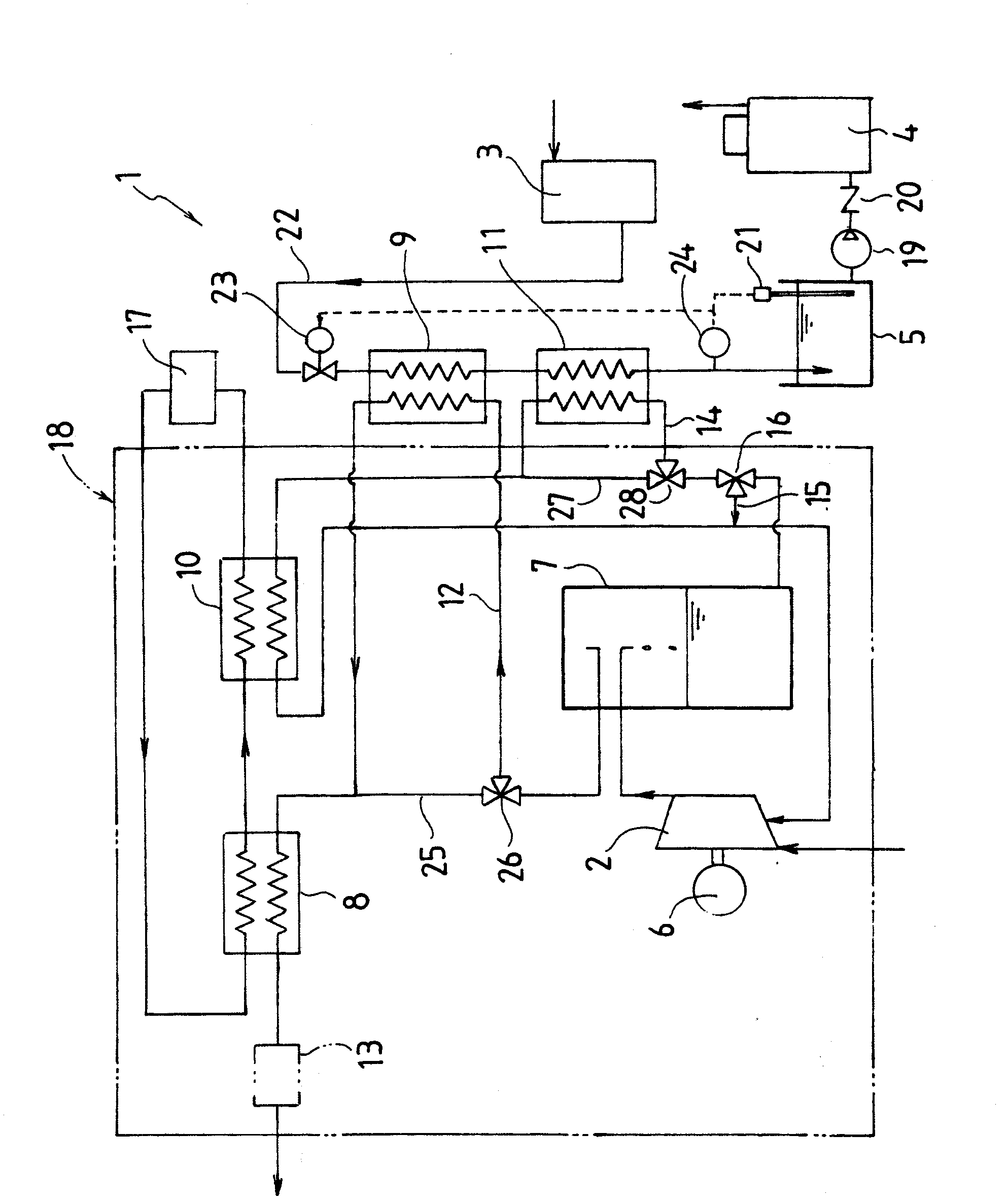
[0078] figure 2 It is a schematic diagram showing Example 2 of the heat recovery system 1 of the present invention.
[0079] The heat recovery system 1 of the second embodiment is also basically the same as the heat recovery system 1 of the first embodiment. Therefore, the following description will focus on the differences between the two, and the corresponding parts will be described with the same reference numerals.
[0080] In said embodiment 1, the compressed air from the compressor 2 is sent to the first air cooler 8 through the second air cooler 9, but in this embodiment 2, the compressed air can be passed through the second air cooler. 9 or the switching of delivery without passing through the second air cooler 9 , or the distribution ratio of passing through the second air cooler 9 or not passing through the second air cooler 9 can be changed. For this reason, the inlet side and the outlet side of the second air cooler 9 are connected by a branch air supply passage...
Embodiment 3
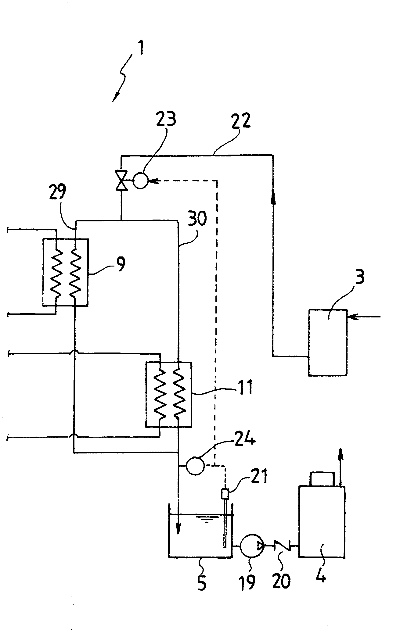
[0083] image 3 It is a schematic diagram showing Example 3 of the heat recovery system 1 of the present invention, and shows only the modified parts different from Example 1 or Example 2.
[0084] The heat recovery system 1 of the present Example 3 is also basically the same as the heat recovery systems 1 of the above-mentioned Example 1 and the above-mentioned Example 2. Hereinafter, the difference between the two will be described mainly, and the corresponding parts will be described with the same reference numerals.
[0085] In the first embodiment and the second embodiment, the second air cooler 9 and the second oil cooler 11 are connected in series so that the water leading to the water supply tank 5 flows sequentially, but in the third embodiment Among them, the second air cooler 9 and the second oil cooler 11 are arranged in parallel, and the water branch leading to the water supply tank 5 flows to the second air cooler 9 and the second oil cooler 11 .
[0086] Speci...
PUM
 Abstract
Description
Claims
Application Information