
Tensioning device with a cylindrical latching system

A tensioning device, cylinder technology, applied in the direction of transmission, belt/chain/gear, mechanical equipment, etc., to achieve the effect of improving manufacturing quality and manufacturing accuracy

Active Publication Date: 2012-05-16
SCHAEFFLER TECH AG & CO KG
View PDF6 Cites 5 Cited by
  • Summary
  • Abstract
  • Description
  • Claims
  • Application Information

AI Technical Summary

Problems solved by technology

[0005] This cylindrical locking system requires a proportionally large construction space length and is therefore only conditionally suitable for use when there is only a small construction space

Method used


Image

  • Tensioning device with a cylindrical latching system
  • Tensioning device with a cylindrical latching system
  • Tensioning device with a cylindrical latching system

Examples


Embodiment Construction

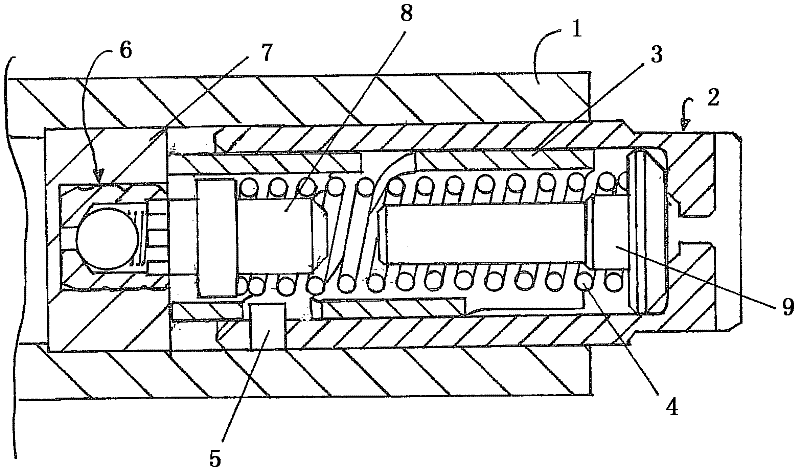
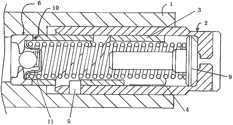
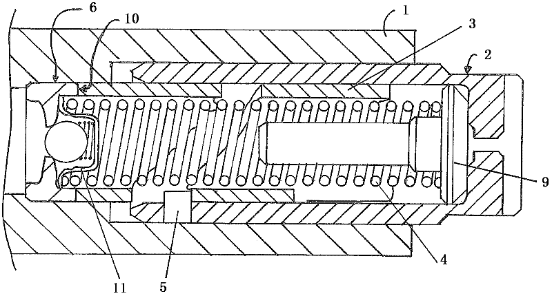
[0020] A tensioning device such as that described in document EP 1 498 580 B1 is shown in FIG. 1 . The piston 2 is mounted slidingly in the housing 1 and serves to tension an endless traction device (not shown) in the engine. Arranged inside the piston 2 is a cylinder 3 in the form of a stop sleeve. The locking sleeve has a helical toothing, into which an engagement element 5 connected to the piston 2 engages in a form-fitting manner. Arranged inside the locking sleeve is a compression spring 4 which bears against the cartridge 8 at a first end and rests on a ventilation plug 9 at a second end. The ventilation plug 9 is assigned to that side of the piston 2 protruding from the housing 1 and allows air to escape from the interior of the piston 2 . The cartridge 8 bears against the non-return valve 6 . In order that oil can flow from an oil supply chamber (not shown) via check valve 6 into the interior of piston 2 , paths, for example flow channels, are provided in the interi...


PUM


Abstract

A tensioning device for an endless traction element in an engine. The tensioning device has a housing, a plunger, which can he moved in the housing, a compression spring arranged in the plunger, a nonreturn valve arranged between the plunger and the housing, a cylinder arranged in the plunger, and an engagement element. The plunger and the cylinder are connected to one another by a latching system via engagement of the engagement element, and the cylinder is connected materially to the nonreturn valve.

Description

technical field [0001] The invention relates to a tensioning device with a cylindrical locking system according to the preamble of claim 1 . Background technique [0002] In the force transmission mechanism thus configured to transmit the rotational movement of the crankshaft to one or more camshafts or other components of the internal combustion engine of the vehicle via endless traction means, such as a chain, the tension of the endless traction means is thus kept constant, That is, there is provided a tensioning device that applies tension to the endless traction device. The tensioning force transmitted to the endless traction device via the piston of the tensioning device can be provided, for example, by means of a cylindrical compression spring. In the event of slackening of the endless traction means, the piston pre-tensioned by the pressure spring moves forward in order to apply pressure to the endless traction means, so that the endless traction means again bears ag...

Claims


Application Information

Patent Timeline
Patent Type & Authority Applications(China)
IPC IPC(8): F16H7/08
CPCF16H2007/0817F16H2007/0859F16H2007/0806F16H7/0848
Inventor 克里斯蒂安·哈特曼彼得鲁斯·胡贝图斯·克鲁恩
Owner SCHAEFFLER TECH AG & CO KG
Learn More