Method for manufacturing prepreg for printed wiring board and device for manufacturing prepreg for printed wiring board

A technology for printed wiring boards and manufacturing methods, applied in the field of manufacturing prepregs for printed wiring boards and manufacturing devices for prepregs for printed wiring boards, capable of solving the problems of insufficient removal of air bubbles, poor productivity of prepregs, and discharge Problems such as slow substrate plate 3 conveying speed, to achieve the effect of speeding up conveying speed, improving productivity, and preventing residual air bubbles

Active Publication Date: 2012-05-16
PANASONIC CORP
View PDF5 Cites 1 Cited by
  • Summary
  • Abstract
  • Description
  • Claims
  • Application Information

AI Technical Summary

Problems solved by technology

Therefore, if the conveyance speed of the substrate sheet 3 is faster than the immersion speed of the resin liquid 4, the air bubbles in the resin liquid 4 cannot be sufficiently removed, and as a result, there is a problem that air bubbles remain in the prepreg.
That is, in order to remove air bubbles in the resin liquid 4, it is necessary to slow down the conveyance speed of the base plate 3, thereby causing a problem that the productivity of the prepreg deteriorates.

Method used


Image

  • Method for manufacturing prepreg for printed wiring board and device for manufacturing prepreg for printed wiring board
  • Method for manufacturing prepreg for printed wiring board and device for manufacturing prepreg for printed wiring board
  • Method for manufacturing prepreg for printed wiring board and device for manufacturing prepreg for printed wiring board

Examples


Embodiment approach 1

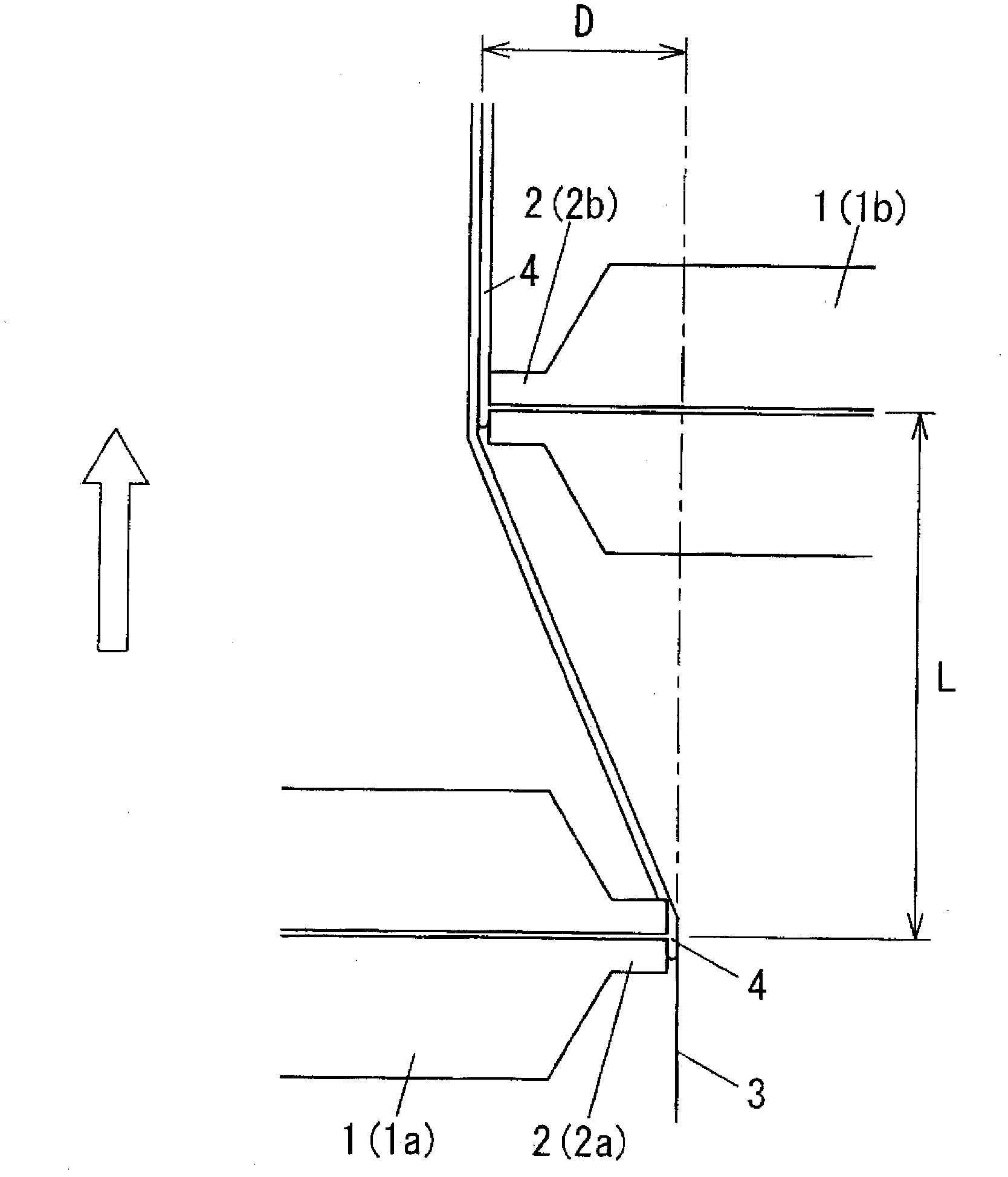
[0028] figure 1 An example of the manufacturing method of the prepreg for printed wiring boards of this invention, and its apparatus is shown in . This prepreg manufacturing apparatus for printed wiring boards is equipped with the 1st coating apparatus 1a and the 2nd coating apparatus 1b which are two coating machines. The base plate 3 is conveyed in the arrow direction (from bottom to top) in the figure so as to pass between the two coating machines, and the resin liquid 4 is applied to both surfaces individually. In addition, although the same coater was used for the 1st coater 1a and the 2nd coater 1b in this embodiment, you may use a different coater.

[0029]The first coating device 1 a and the second coating device 1 b each have a coating tip 2 , and each coating tip 2 is formed elongatedly along the width direction of the base plate 3 . Moreover, the first coating tip 2a as the coating tip 2 of the first coating device 1a protrudes toward one surface of the base plat...

Embodiment approach 2

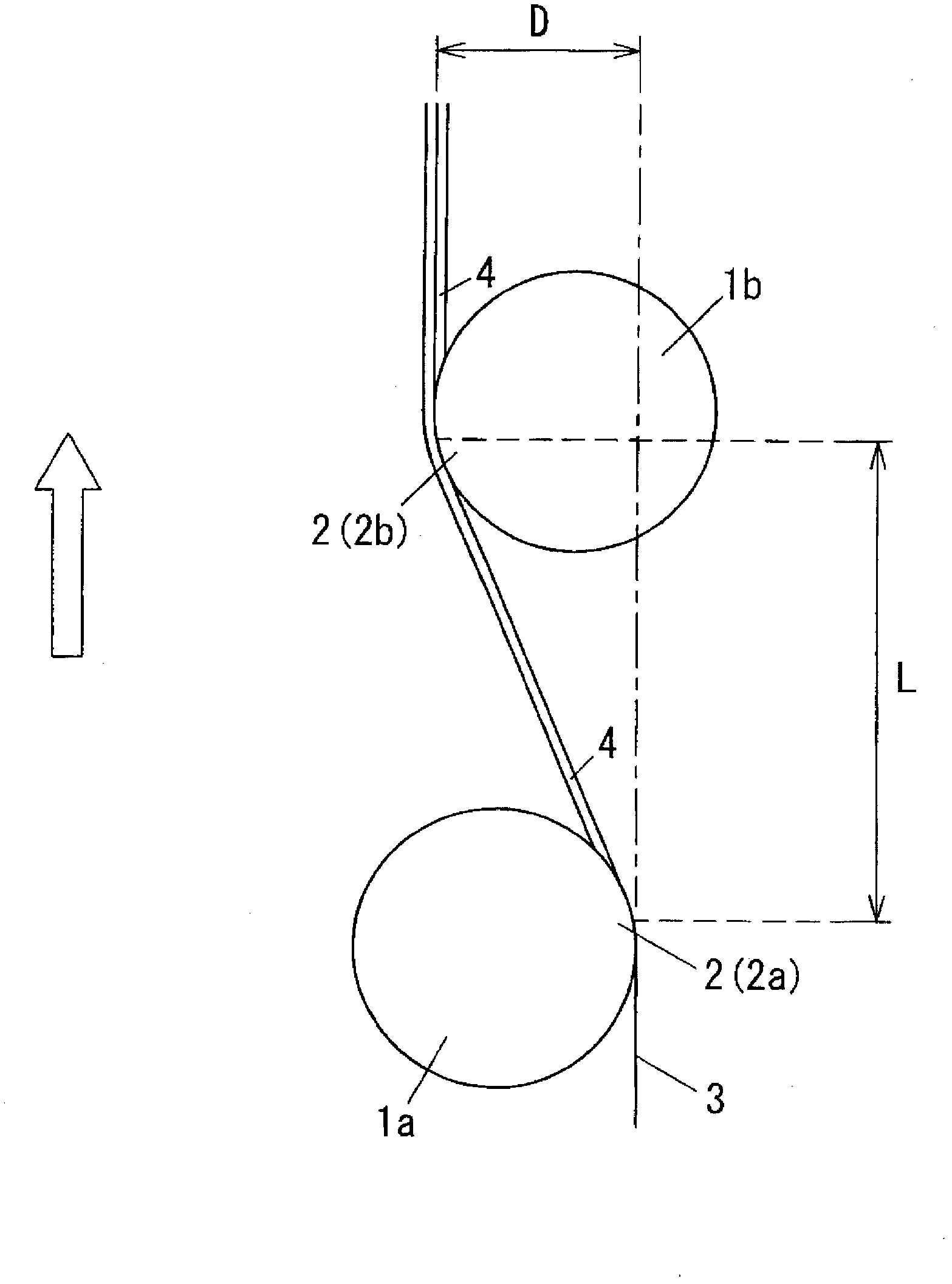
[0045] In the first embodiment described above, an example in which a coater is used as the first coater 1 a and the second coater 1 b has been described. In this embodiment, an example using a roll coater as the first coating device 1a and the second coating device 1b will be described.

[0046] image 3 The main part of the manufacturing method of the prepreg for printed wiring boards of this embodiment, and the apparatus is shown. In the present embodiment, as the first coating device 1 a and the second coating device 1 b , a roll coater, which is a cylindrical device, is used respectively, and the outer peripheral surface of the cylinder serves as the coating tip 2 . And between the 1st coating front end part 2a and the 2nd coating front end part 2b, the distance L between coatings is provided along the conveyance direction of the substrate sheet 3, as these coating front end parts 2 and the substrate sheet 3 The overlap distance in the vertical direction, set the front ...

Embodiment

[0050]Prepregs were manufactured under the conditions shown in Table 1 using a prepreg manufacturing apparatus including two coating devices 1 that independently coat both surfaces of the base plate 3, and were evaluated. That is, with the coating device 1 shown in Table 1, the distance between coatings L, the overlapping distance D, the conveyance speed of the base plate 3, the line tension when the base plate 3 is transported, and the distance from the first coater 1a The weight ratio of the discharge amount of the resin solution per unit time with the second coating device 1b is used to apply the resin solution 4 to the base plate 3 to produce a prepreg, and evaluate the impregnation of the resin solution 4 under various conditions, and , Measure the resin film thickness ratio of the prepreg, and judge by comprehensively evaluating whether the prepreg for printed wiring boards is good or not.

[0051] The evaluation of the immersion property of the resin liquid 4 was based ...


PUM


Abstract

The present invention has been aimed to propose a process and a device of fabricating a prepreg for a printed circuit board which are capable of controlling respective thicknesses of resin layers on the opposite surfaces of a resultant prepreg, removing air bubbles from the resultant prepreg, and improving productivity. The present invention is a process of resin-coating the opposite surfaces of an elongated substrate sheet 3. The process includes the steps of: feeding the substrate sheet 3 while tensioning the same in a feeding direction along the length of the substrate sheet 3; coating, by the coating head 2 of the first dispenser 1a, one surface of the substrate sheet 3 with the fluid resin 4 while pressing against the one surface to bend the substrate sheet 3; and subsequently coating, by the coating head 2 of the second dispenser 1b, the other surface of the substrate sheet 3 with the fluid resin 4 while pressing against the other surface to bend the substrate sheet 3. A die coater and a roll coater can be used as the first dispenser 1a and the second dispenser 1b.

Description

technical field [0001] The present invention relates to a method for manufacturing a prepreg for a printed wiring board by applying a resin liquid to a base plate made of glass fiber or the like, and a printed wiring board provided with a device for applying the resin liquid to a base plate Manufacturing devices using prepregs. Background technique [0002] As a method of manufacturing a prepreg for printed wiring boards, a dip squeeze method and a dip coating / knife coating (dip squeeze method) are conventionally known. In these methods, the base plate is dipped into a resin solution obtained by dissolving the resin that forms the insulating material, and after the resin liquid is immersed in the base plate, it is dried to make it semi-cured, and then adhered to the surface of the base plate. It is a method to adjust the film thickness of the prepreg resin film by removing the excess resin film. Such a method can transport the base plate at a good transport speed, and can ...

Claims


Application Information

Patent Timeline
Patent Type & Authority Applications(China)
IPC IPC(8): C08J5/24H05K3/00
CPCH05K2203/1572H05K2201/029H05K2203/1545H05K1/0366H05K2203/0759C08J5/24B29B11/06
Inventor 松崎义则藤田和彦田代雅也小林真也
Owner PANASONIC CORP
Why Eureka
Try Eureka