Technology for sampling suspension high voltage of depressed collector of traveling wave tube and implementation method of technology

A collector and traveling wave tube technology, applied in the direction of regulating electrical variables, control/regulating systems, instruments, etc., can solve problems such as low efficiency

Inactive Publication Date: 2012-05-23
THE 724TH RES INST OF CHINA SHIPBUILDING IND
View PDF2 Cites 7 Cited by
  • Summary
  • Abstract
  • Description
  • Claims
  • Application Information

AI Technical Summary

Problems solved by technology

But traveling wave tubes also have serious defects, that is, the efficiency is very low, usually not more than 15%.

Method used


Image

  • Technology for sampling suspension high voltage of depressed collector of traveling wave tube and implementation method of technology
  • Technology for sampling suspension high voltage of depressed collector of traveling wave tube and implementation method of technology
  • Technology for sampling suspension high voltage of depressed collector of traveling wave tube and implementation method of technology

Examples


Embodiment Construction

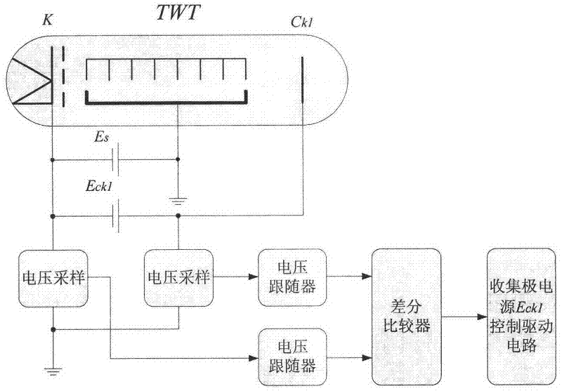
[0008] see figure 1 , Es is the slow-wave line high-voltage power supply, ECk1 is the collector high-voltage power supply, the cathode K of the traveling wave tube is a negative high voltage to the ground, the collector Ck1 is opposite to the cathode plus a positive high voltage ECk1, and ECk1 is suspended to the ground. In order to realize the steady voltage control of ECk1 at the ground potential end, its voltage must be isolated and sampled.

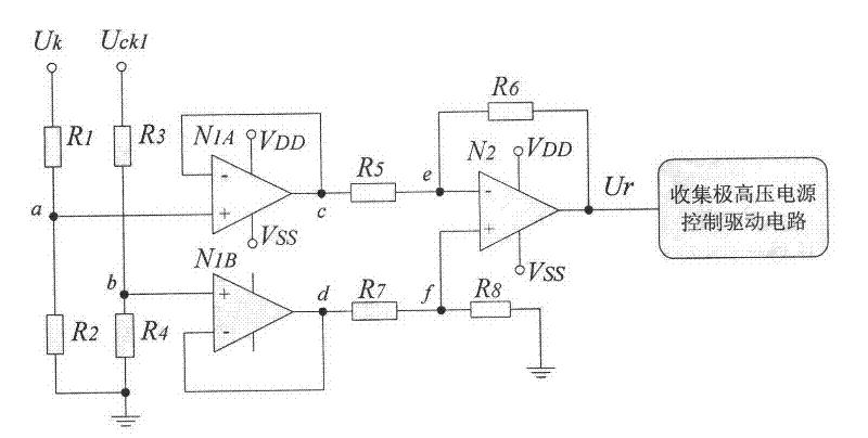
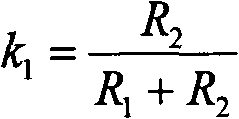
[0009] see figure 2 , Uk and Uck1 are the voltages of the cathode and the collector to the ground respectively, both of which are negative values. R1 and R2 form the cathode negative high-voltage partial pressure sampling circuit, and R3 and R4 form the collector negative high-voltage partial pressure sampling circuit, so their partial pressure ratios are:

[0010] k 1 = R 2 R 1 ...


PUM


Abstract

The invention relates to a technology for sampling a suspension high voltage of a depressed collector of a traveling wave tube and an implementation method of the technology. A functional block diagram for implementing the technology is shown in figures. A tube body having a ground potential is sampled with high voltages which are applied to a cathode and a collector of the traveling wave tube to obtain two low-voltage signals, wherein the ground potential is a reference potential; a differential comparator converts a difference value of the two low-voltage signals into a voltage signal; the voltage is in proportion to voltage difference between the high voltages which are applied to the ground by the cathode and the collector, namely in proportion to an output voltage of a high voltage power supply of the collector; and the voltage signal serving as a feedback signal is sent to a control driving circuit, so that the voltage stabilizing control of the suspension high voltage of the collector at a ground potential end is realized. The invention provides an effective technical way for improving the voltage stabilizing accuracy and load response capacity of a suspension high voltage power supply of the collector of a one-stage or multi-stage depressed collector traveling wave tube, and researching a high-efficiency, high-reliability and high-power traveling wave tube transmitter.

Description

technical field [0001] The invention belongs to the application technology of a special power supply and an electric vacuum tube, and relates to a technology and a realization method of a traveling wave tube step-down collecting pole suspended high-voltage sampling. Background technique [0002] Traveling wave tube (TWT) is widely used in radar, electronic countermeasures, communication and other fields because of its wide operating frequency band, instantaneous bandwidth and high gain. But traveling wave tubes also have serious defects, that is, the efficiency is very low, usually not more than 15%. For high-power or special occasions (such as airborne and missile-borne radars), traveling wave tube transmitters mostly use one-stage or multi-stage step-down collector traveling wave tubes to improve efficiency due to consideration of factors such as power supply and heat dissipation, such as two-stage The efficiency of the step-down collector traveling wave tube can reach mo...

Claims


Application Information

Patent Timeline
Patent Type & Authority Applications(China)
IPC IPC(8): G05F1/565
Inventor 崔海安
Owner THE 724TH RES INST OF CHINA SHIPBUILDING IND
Why Eureka
Try Eureka