Light touch electronic power switch circuit

An electronic power supply and switching circuit technology, applied in the direction of electric switches, circuits, electrical components, etc., can solve the problems of waste of electric energy, failure to realize intelligent control of home appliances, and large operating noise of mechanical structure, so as to achieve convenient use and intelligent home appliances The effect of controlling and eliminating potential safety hazards

Inactive Publication Date: 2012-05-23
ZHEJIANG WANSHENG ELECTRIC
View PDF4 Cites 2 Cited by
  • Summary
  • Abstract
  • Description
  • Claims
  • Application Information

AI Technical Summary

Problems solved by technology

[0002] The existing AC power switch generally switches the on-off state of the power output terminal and the power input terminal through a mechanical structure, and the mechanical structure has defects such as high operating noise; in addition, if the user forgets to turn off the power switch when the power is suddenly cut After the power is received, the electrical appliances work automatically, resulting in waste of electric energy and potential safety hazards
In addition, the purely mechanical power switch cannot control the opening or closing of the switch through remote control, etc., and cannot realize the intelligent control of home appliances.

Method used


Image

  • Light touch electronic power switch circuit
  • Light touch electronic power switch circuit
  • Light touch electronic power switch circuit

Examples


Embodiment 1

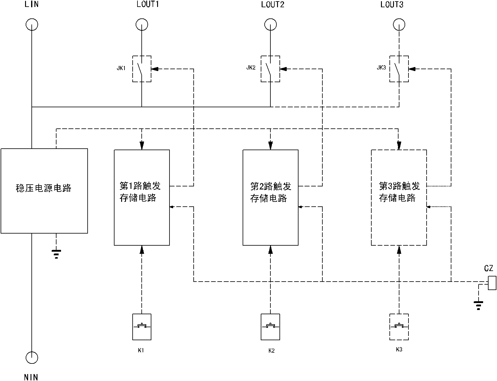
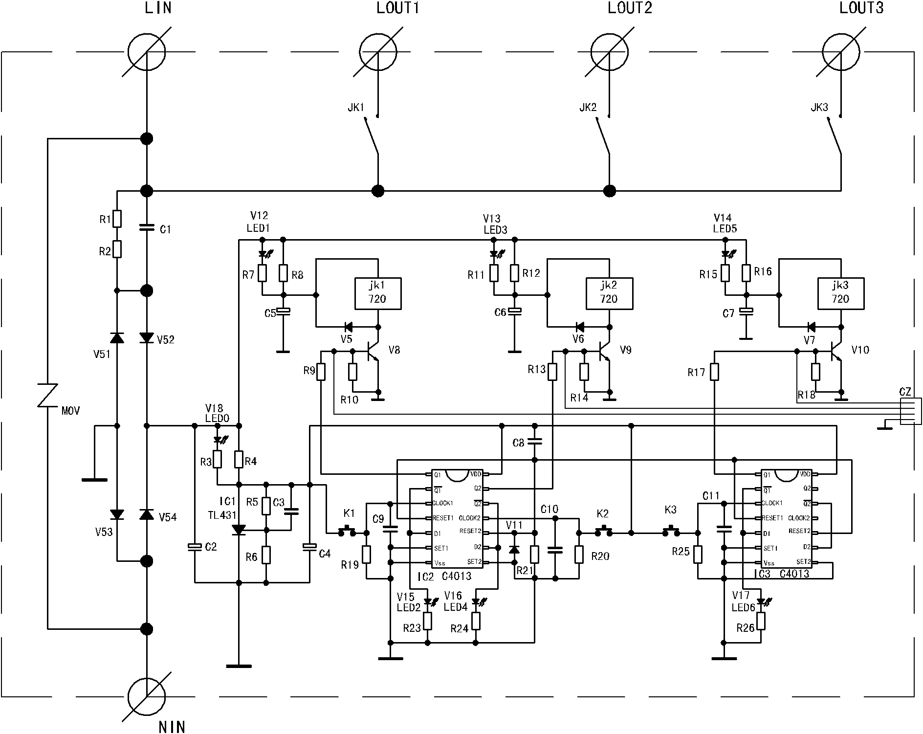
[0021] refer to figure 1 , this embodiment takes three live wire output terminals as an example. The light touch electronic power switch circuit in this embodiment includes a power live wire input terminal LIN and three power supply live wire output terminals (LOUT1, LOUT2, LOUT3). Each power output terminal passes through An electromagnetic switch is connected to the input terminal of the power supply. The electromagnetic switch is controlled by the trigger storage circuit. The input terminal of the trigger storage circuit is connected with light touch buttons (K1, K2, K3). The solenoid switch state changes once. The light touch electronic power switch circuit also includes a voltage stabilized power supply circuit that provides DC regulated power for each trigger storage circuit. Theoretically, the number of live wire output terminals of the light touch electronic power switch circuit of the present invention can be expanded arbitrarily according to needs.

[0022] The elec...

Embodiment 2

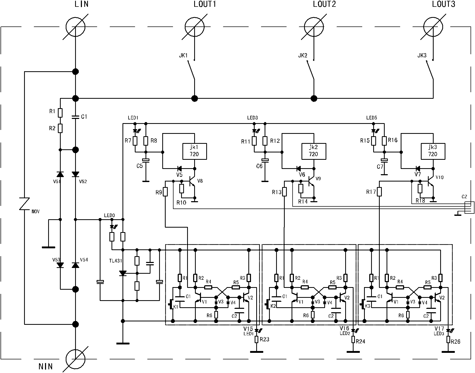
[0030] and image 3 , the trigger storage circuit of this embodiment adopts discrete components to form a bistable flip-flop, and the rest of the circuit structure is basically the same as that of Embodiment 1. Still taking the first trigger storage circuit as an example, the trigger storage circuit includes discrete components (R1, R2 , R3, R4, R5, R6, C1, C2, V1, V2, V3, V4) composed of a bistable flip-flop, the collector of the triode V1 is connected to the output terminal of the regulated power supply circuit through the resistor R2, and the base of the triode V1 The collector of the triode V2 is connected through the resistor R5, and the emitter of the triode V1 is grounded; the collector of the triode V2 is connected to the output terminal of the regulated power supply circuit through the resistor R3, and the base of the triode V2 is connected to the collector of the triode V1 through the resistor R4, and the transistor V2 The emitter of the diode V3 and the diode V4 are...


PUM


Abstract

The invention provides a light touch electronic power switch circuit that comprises a power supply live wire input terminal, a power supply zero line input terminal and at least one path of a power supply fire wire output terminal. All paths of power supply fire wire output terminals are connected with electromagnetic switches and the power supply live wire input terminal; the electromagnetic switches are controlled by trigger storage circuits; and input terminals of the trigger storage circuits are connected with light touch buttons. When the light touch buttons are closed once, output states of the trigger storage circuits are overturned once, so that the electromagnetic switch states are changed once. Besides, a voltage-stabilized source circuit that is used for providing a direct current power supply for all the trigger storage circuits and coils of the electromagnetic switches is provided. According to the invention, beneficial effects are as follows: an output signal of a trigger storage circuit is overturned once by one-time motion of a light touch button, so that an on-off state of a power supply live wire output terminal is changed once; therefore, the circuit can be used conveniently; moreover, when the power supply live wire output terminal is power off and then is power on, an electromagnetic switch can be maintained to be in a turn-off state, so that power can be saved and the potential safety hazard can be eliminated.

Description

technical field [0001] The invention relates to an internal circuit structure of a power switch, in particular to a light touch electronic power switch circuit. Background technique [0002] The existing AC power switch generally switches the on-off state of the power output terminal and the power input terminal through a mechanical structure, and the mechanical structure has defects such as high operating noise; in addition, if the user forgets to turn off the power switch when the power is suddenly cut After the power is received, the electrical appliances work automatically, resulting in waste of electric energy and potential safety hazards. In addition, the purely mechanical power switch cannot control the opening or closing of the switch by means of remote control, etc., and cannot realize intelligent control of home appliances. Contents of the invention [0003] In view of the above-mentioned deficiencies in the prior art, the object of the present invention is to p...

Claims


Application Information

Patent Timeline
Patent Type & Authority Applications(China)
IPC IPC(8): H01H13/02H01H9/54
Inventor 黄华道陆华洋
Owner ZHEJIANG WANSHENG ELECTRIC
Why Eureka
Try Eureka