Low-loss low-speed permanent magnet synchronous motor

A permanent magnet synchronous motor, low-loss technology, applied in synchronous motors with static armatures and rotating magnets, magnetic circuit rotating parts, magnetic circuit shape/style/structure, etc., can solve the problem of high harmonic electromotive force. Loss, inconvenient insertion of stator windings, large cogging torque, etc., to achieve the effect of improving assembly work efficiency, shortening production period, and reducing heat

Inactive Publication Date: 2012-05-23
京能新能源科技(上海)有限公司
View PDF7 Cites 2 Cited by
  • Summary
  • Abstract
  • Description
  • Claims
  • Application Information

AI Technical Summary

Problems solved by technology

[0006] The purpose of the present invention is to solve the technical problems of high stator copper consumption, large cogging torque and complicated wiring of existing permanent magnet synchronous motors
[0007] Another object of the present invention is to solve the problem of inconvenient embedding of stat

Method used


Image

  • Low-loss low-speed permanent magnet synchronous motor
  • Low-loss low-speed permanent magnet synchronous motor
  • Low-loss low-speed permanent magnet synchronous motor

Examples


Embodiment 1

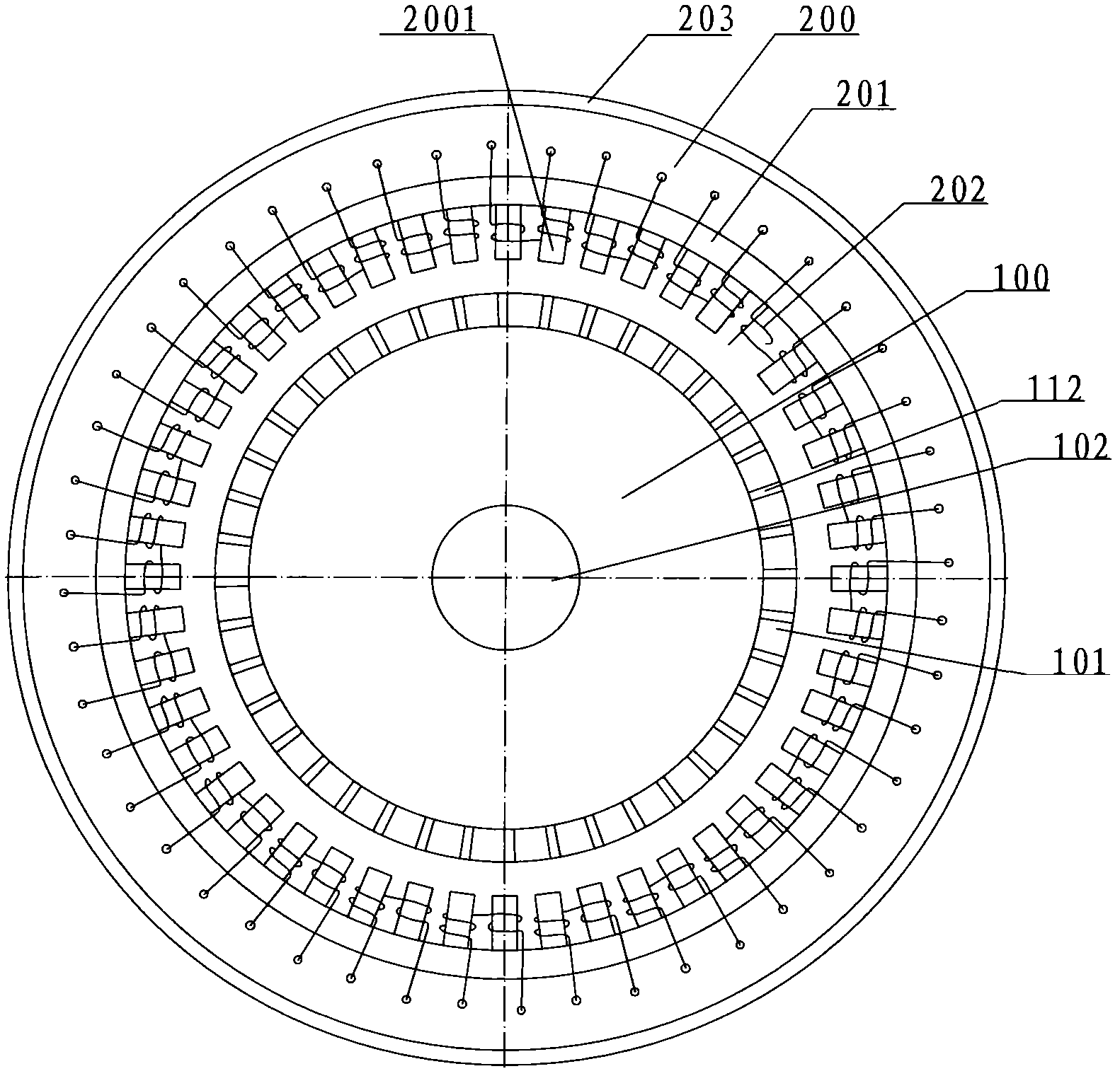
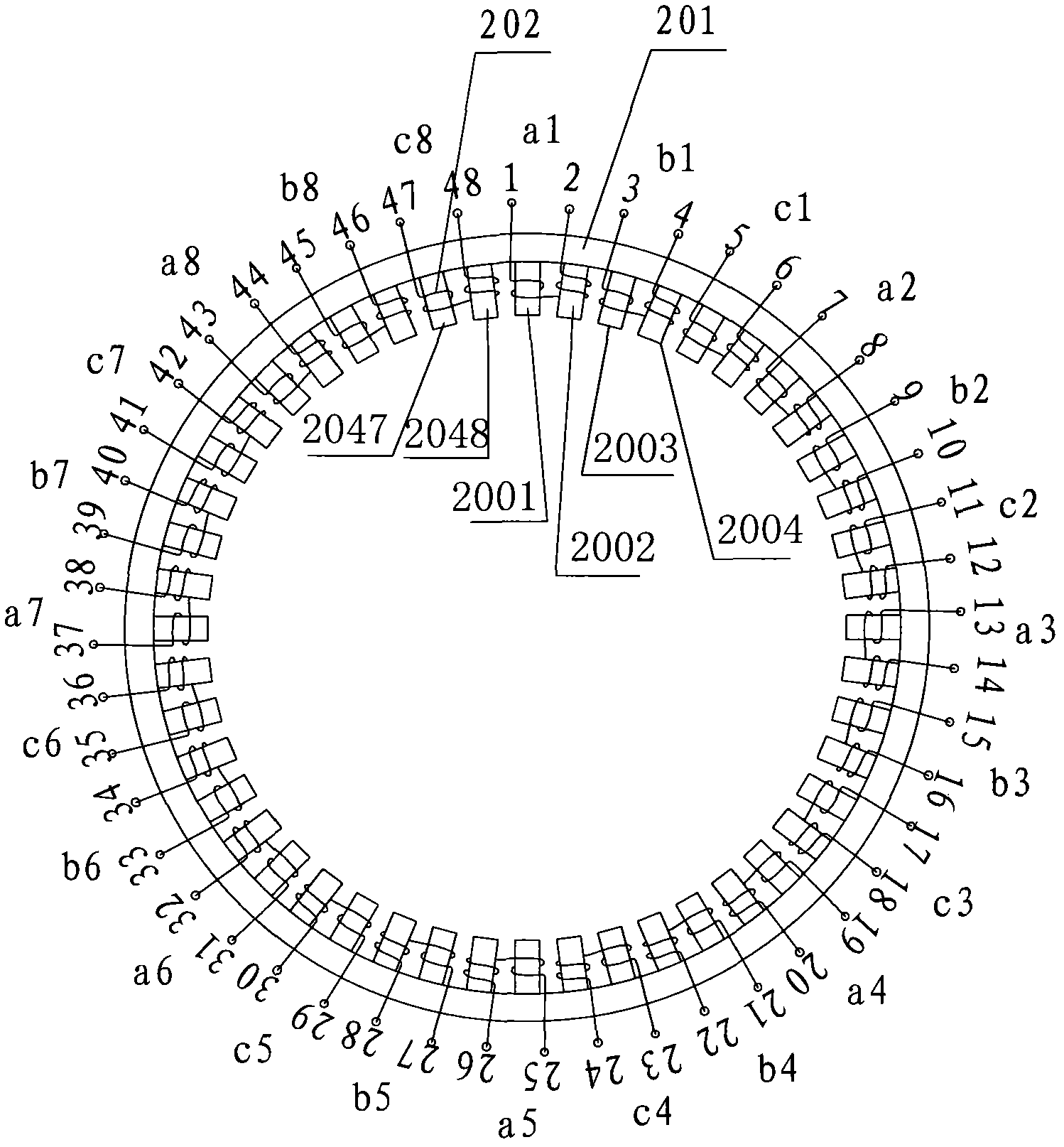
[0037] Embodiment one, see figure 1 , the figure shows a low-loss low-speed permanent magnet synchronous motor according to the present invention, which includes a rotor 100 and a stator 200, the stator 200 includes a casing 203, a stator core 201 and a stator winding 202, and the rotor 100 includes a rotor body 101 , the rotating shaft 102, the matching ratio of the pole slots of the motor is 5:6, wherein the stator core 201 has 48 teeth 2001, 2002, ... 2048 ( figure 2shown), and the surface of the rotor has 40 pairs of permanent magnets 112; the stator structure is specifically referred to figure 2 , including a stator core 201 and a stator winding 202. In this embodiment, the motor phase number m is 3, and the stator core 201 has teeth 2001, 2002, 2003..., 2047, 2048 for coil nesting, and the number of teeth is 48. S=2nm, n is 8; Each phase winding is made up of a coil unit, and in the present invention, coil unit a1 is the same single-tooth semi-winding that winds on tw...

Embodiment 2

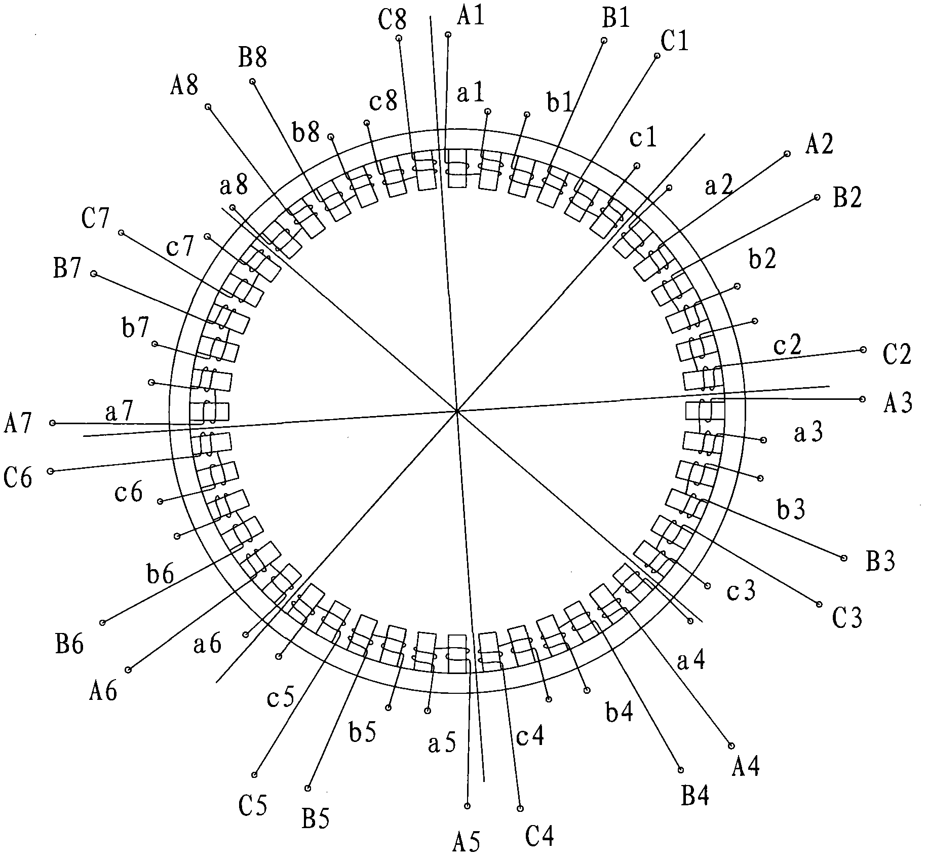
[0045] Embodiment two, see Figure 7 , the figure shows the same as that of Example 1 image 3 Different stator winding connection methods shown in : connect the first group of three-phase winding units (a1, b1, c1) and the second group of three-phase winding units (a2, b2, c2) in series among the eight three-phase winding units, The third group of three-phase winding units (a3, b3, c3) and the fourth group of three-phase winding units (a4, b4, c4) are connected in series, the fifth group and the sixth group are connected in series, the seventh group and the eighth group are connected in series, and so on Constitute four sets of independent three-phase windings. combine figure 2 and Figure 7 , taking the first group as an example to illustrate its connection method. For clarity of description, the left end of the coil unit a1 is defined as the head end, and the right end is defined as the end, and the adjacent end of the coil unit b1 and a1 is defined as the head end, an...

Embodiment 3

[0046] Embodiment three, see Figure 8 , the figure shows the same as that of Example 1 image 3 and embodiment two Figure 7 The different stator winding connections shown in : connect the first, second, third, and fourth sets of three-phase winding units (a1, b1, c1), (a2, b2, c2), (a3, b3, c3); (a4 , b4, c4) are connected in series as an independent three-phase winding (A1, B1, C1), and the fifth, sixth, seventh, and eighth three-phase winding units (a5, b5, c5), (a6, b6, c6 ), (a7, b7, c7); (a8, b8, c8) are connected in series to form an independent three-phase winding (A2, B2, C2); take the first three-phase winding (A1, B1, C1) as an example : In the three-phase winding unit (a1, b1, c1), the head end of the coil unit a1, the end of b1, and the head end of c1 are respectively connected to the lead-out ends, and the end of a1 is connected to the three-phase winding unit (a2, b2, c2) The end of the coil unit a2; the head end of the coil unit b1 is connected to the head ...


PUM


Abstract

The invention relates to a low-loss low-speed permanent magnet synchronous motor, which comprises a rotor and a stator. The match ratio of polar troughs of the motor is 5:6; the stator comprises a stator core and a stator winding; the tooth number of the stator core S is equal to 2nm, wherein m is a phase number and n is an even number more than or equal to 2; the stator winding is a polyphase winding, and each phase of winding at least consists of a coil unit; the coil unit consists of single-tooth half windings having the same winding direction on two adjacent teeth; the tail ends of the single-tooth half windings on the two teeth in the coil unit are connected; and leads of the single-tooth half windings on the two adjacent teeth of every two adjacent coil units are all taken as output ends or input ends. The low-speed permanent magnet synchronous motor can effectively reduce motor loss and reduce the torque of a tooth space, and the efficiency of the motor is improved.

Description

technical field [0001] The invention relates to a motor, in particular to a low-loss low-speed permanent magnet synchronous motor. Background technique [0002] Due to its long life and easy maintenance, permanent magnet motors are more and more widely used with the rapid development of electronic technology, such as: wind power generation, hybrid vehicles, aviation, electronic equipment, mining and other technical fields. [0003] Existing low-speed permanent magnet synchronous generators or motors are mainly composed of stators, rotors, bearings and casings. The stator is generally composed of silicon steel sheets stacked into a stator core, and the stator winding is in the core slot. Among them, the stator windings generally adopt distributed windings, which have the problems of complex off-line and long manufacturing cycle. Due to the long coil ends, the stator copper consumption is high. In order to solve the complex problem of distributed winding off-line, there are ...

Claims


Application Information

Patent Timeline
IPC IPC(8): H02K21/14H02K3/28H02K1/27H02K1/28
Inventor 汉斯・鲁道夫・西格里斯特史人杰
Owner 京能新能源科技(上海)有限公司
Why Eureka
Try Eureka