
Device for transferring a band-shaped weft material

A weft yarn and ribbon-shaped technology, which is applied in the field of devices for introducing components, can solve the problems of damaging the ribbon-shaped weft yarn, troublesome laser mechanical drive, and large structural space.

Active Publication Date: 2012-05-23
LINDAUER DORNIER GMBH
View PDF9 Cites 12 Cited by
  • Summary
  • Abstract
  • Description
  • Claims
  • Application Information

AI Technical Summary

Problems solved by technology

However, due to the relative movement of the tape-shaped weft yarn between the rollers, the tape-shaped weft yarn may be damaged
[0007] DE 528 345 and DE 5 5 3 886 show devices for feeding weft threads onto loom protection, but they require a large construction space and they are mechanically driven by a laborious laser

Method used


Image

  • Device for transferring a band-shaped weft material
  • Device for transferring a band-shaped weft material
  • Device for transferring a band-shaped weft material

Examples


Embodiment Construction

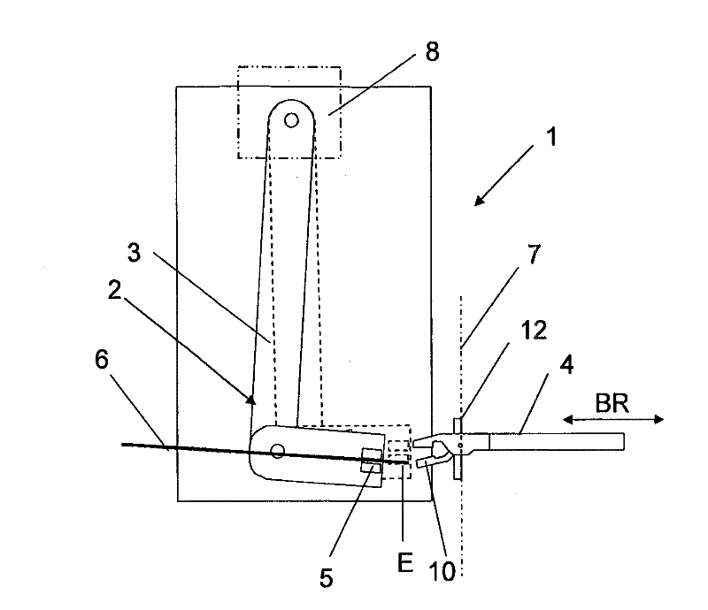
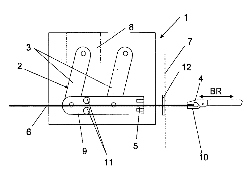
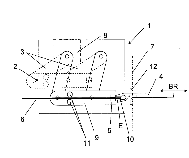
[0035] figure 1 A device 1 according to the prior art is shown for feeding strip-shaped weft threads 6 with a pivot unit 2 having only one pivot arm 3 . The device 1 feeds a weft thread 6 from a delivery unit (not shown here) to the insertion part 4 of the weaving machine. The delivery unit can be formed by storage bobbins, accumulators or pre-bobbins or feeders, which respectively unwind the required weft yarn lengths from bobbins and make them available. The insertion element 4 here is formed by the weft gripper of the weaving machine, but it can likewise be inserted by means of transmitters or other insertion elements. The device 1 comprises a clamping device 5 , which clamps and fixes a weft thread 6 after the weft thread has been inserted and cut for this purpose, for subsequent relaying of the weft thread in front of the insertion element 4 . The insertion element 4 receives the free end of the weft thread 6 on the device-side product edge 7 of the device 1 and connect...


PUM


Abstract

The invention relates to a device (1) for transferring a preferably band-shaped weft material (6) from a feed unit to an insertion element (4) of a weaving machine, comprising a clamping device (5) for clamping a free end (E) of the weft material (6). The clamping device (6) can be moved substantially in the direction (BR) of motion of the insertion element (4) between at least two different operating positions. The device (1) contains a drive (8) for moving the clamping device (5). In a method for transferring a preferably band-shaped weft material (6) from a coil or a feed unit to an insertion element (4) of a weaving machine, a free end (E) of the weft material (6) is clamped in a clamping device (5), the free end (E) is transferred to the insertion element (4), then the clamping device (5) is opened, and the weft material is inserted. The clamping device (5) is moved substantially in the direction of motion of the insertion element (4) between at least two different operating positions by means of a drive (8).

Description

technical field [0001] The invention relates to a device and a method for feeding strip-shaped weft threads from a delivery unit to an introduction part of a weaving machine. The device comprises a clamping device for clamping the free end of the weft thread. Background technique [0002] Numerous devices are known in the prior art for weaving machines for feeding weft threads to insertion elements, for example grippers of rapier looms. [0003] In WO 2008 / 009332 A1, for the selection of the weft thread, needle-shaped bars with loops are provided, through which the weft threads are respectively guided and brought from the rest position to the working position depending on the weft thread selected. Then the selected weft yarn is brought to the receiving position of the weft gripper by the movable feeder. [0004] EP 0 240 075 B1 describes a device with a weft thread selection device, in which a weft thread clamp is provided which is movable for each weft thread. The weft t...

Claims


Application Information

Patent Timeline
Patent Type & Authority Applications(China)
IPC IPC(8): D03D47/12D03D47/38
CPCD03D41/008D03D47/38D03D47/12
Inventor T.劳坎普H.米勒
Owner LINDAUER DORNIER GMBH
Learn More