Automatic programming device and method

A technology of automatic programming and processing procedures, which is applied in the direction of automatic control devices, feeding devices, program control, etc.

Active Publication Date: 2012-05-23
MITSUBISHI ELECTRIC CORP
View PDF5 Cites 15 Cited by
  • Summary
  • Abstract
  • Description
  • Claims
  • Application Information

AI Technical Summary

Problems solved by technology

[0006] The present invention was made in order to solve the above-mentioned problems, and to obtain an automatic programming device that can program even when the shape of the target part to be processed such as the hole or the

Method used


Image

  • Automatic programming device and method
  • Automatic programming device and method
  • Automatic programming device and method

Examples


Embodiment approach 1

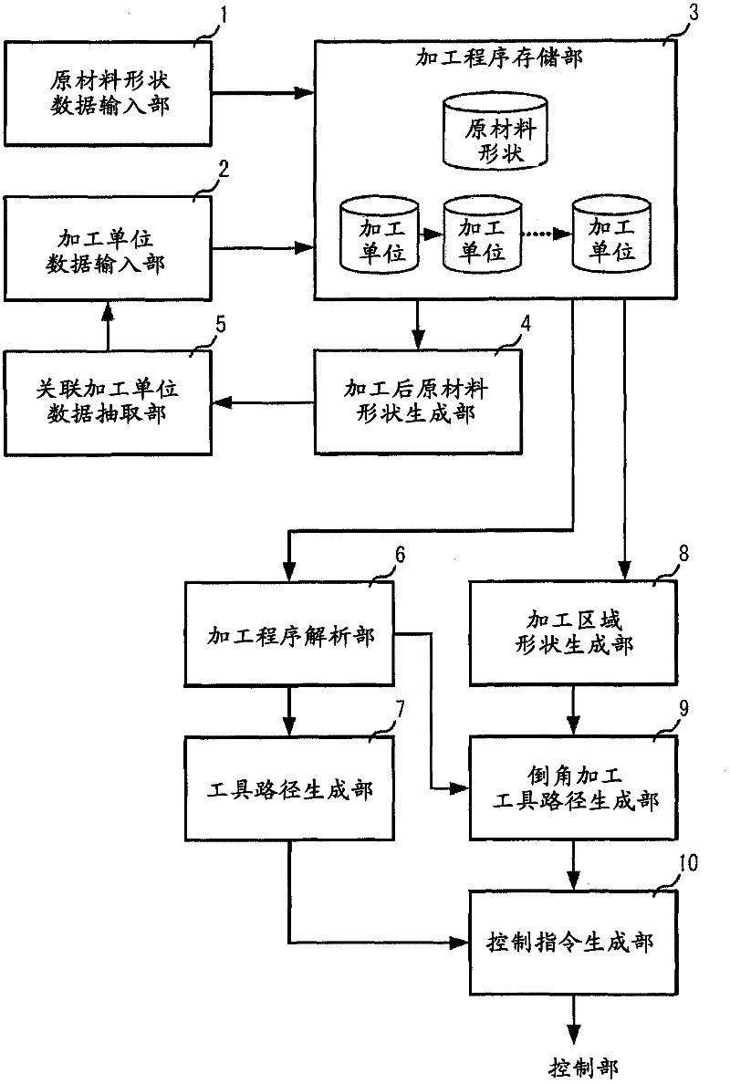
[0035] figure 1 It is a block diagram of the automatic programming device in Embodiment 1 of this invention. The automatic programming device generates control instruction data based on the processing unit data for partial processing of the shape of the raw material, and inputs data including the shape of the processing area, processing method, tool used, processing conditions, etc. for partial processing The processing unit data is analyzed, and the input processing unit data is analyzed to generate control command data for operating the machine tool. exist figure 1 Among them, the automatic programming device is composed of a material shape data input unit 1 , a processing unit data input unit 2 , a machining program storage unit 3 , a processing area shape generation unit 8 , and a control command generation unit 10 .

[0036] The material shape data input unit 1 inputs data defining the shape of the material from outside, and stores the data in the machining program stor...

Embodiment approach 2

[0070] Figure 11 It is a block diagram showing the configuration of the chamfering tool path generator in Embodiment 2 of the present invention. The chamfering toolpath generation unit 9 receives the processing region shape data of the portion to be chamfered from the processing region shape generation unit 8 . In the present embodiment, the content of generating the chamfering machining tool path based on the data related to the edge of the chamfering machining portion input from the machining area shape generating unit 8 will be described in detail. The chamfering tool path generation unit 9 acquires chamfering data from a data storage unit storing data related to chamfering, and generates a chamfering tool path. In the present embodiment, the machining area shape generating unit 8 corresponds to a data storage unit, but may be distributed with the machining program storage unit 3 depending on the content of the acquired data. The chamfering tool path generation unit 9 ac...

Embodiment approach 3

[0133] Figure 23 It is an explanatory diagram of a cross-sectional plane defined in the third embodiment. In Embodiment 2, 5-axis machining is assumed for chamfering toolpath generation, but it can also be applied to 3-axis machining to obtain a toolpath approximately. However, in the case of 3-axis machining, unlike the case of 5-axis machining, the tool posture is constant, so there is a slightly different point in the processing related to the section plane Fij. Points different from Embodiment 2 will be described below.

[0134] like Figure 23 As shown, the section plane Fij in the case of 3-axis machining is defined as passing through the reference point Pij, and transferring the direction vector of the reference point Pij in the edge Ei, that is, the reference vector Vij, to the depth direction perpendicular to the groove (X Direction) the plane generated by the transfer vector Vij' perpendicular to the plane. Specifically, for the reference point Pij obtained by d...


PUM


Abstract

In order to obtain an automatic programming device which makes it easy to define machining-unit data and makes it possible to form an appropriate machining area shape in accordance with the shape of a curve section even if the shape of a part to be machined such as a hole or the edge of a groove, which is formed on a cylindrical surface is a complicated curve, disclosed is an automatic programming device which is provided with a raw-material shape data input unit (1) for inputting raw-material shape data, a machining program storage unit (3) for storing the raw-material shape data and the machining-unit data, a machining-unit data input unit (2) for inputting other machining-unit reference type of machining-unit data, which references the machining area shape data included in the machining-unit data, a machining area shape generating unit (8); for generating machining area shape data associated with the machining-unit data of partial machining on the basis of the raw-material shape data and the machining area shape data referenced by other machining-unit reference type of machining-unit data, and a control command generating unit (10) for generating control command data on the basis of the machining-unit data of the partial machining including the machining area shape data.

Description

technical field [0001] The present invention relates to inputting processing unit data for partial processing including data such as the shape of the processing area, processing method, tool used, and processing conditions, and generating control command information for operating a machine tool based on the input processing unit data An automatic programming device and an automatic programming method. Background technique [0002] In the process of inputting the processing unit data for partial processing including data such as the shape of the processing area, processing method, tools used, and processing conditions, and generating control instruction information for operating the machine tool based on the input processing unit data In the programming device, as the definition method of processing such as chamfering, there is a method of directly specifying the shape of the target part of the processing with a shape element such as a line segment or an arc (for example, ref...

Claims


Application Information

Patent Timeline
IPC IPC(8): G05B19/4097B23Q15/00G05B19/4093
CPCG05B19/40931G05B2219/36327Y02P90/02
Inventor 入口健二三谷由香宫田亮佐藤智典松原晋岩崎隆至
Owner MITSUBISHI ELECTRIC CORP
Why Eureka
Try Eureka