Light-reflecting substrate, substrate which can be mounted in light-emitting element, light-emitting device, and process for production of substrate which can be mounted in light-emitting element

A light-emitting element and manufacturing method technology, applied in the direction of electrical components, semiconductor/solid-state device parts, electric solid-state devices, etc., can solve the problems of reduced reflectivity, silver easy-diffusion glass, and reduced transparency of the glass layer, so as to prevent aging changes Effect

Inactive Publication Date: 2012-05-23
KYOCERA CORP
View PDF8 Cites 3 Cited by
  • Summary
  • Abstract
  • Description
  • Claims
  • Application Information

AI Technical Summary

Problems solved by technology

[0016] However, when the glass paste is coated on the conductor paste containing silver as the main component and fired at the same time, the silver and the glass react during firing, and the silver tends to diffuse to the exposed surface of the glass, etc.
Furthermore, the glass layer is colored (turned yellow) by oxidation or sulfidation of the diffused silver component, the transparency of the glass layer decreases, and the reflectance of light from the metal layer to the outside may decrease.

Method used


Image

  • Light-reflecting substrate, substrate which can be mounted in light-emitting element, light-emitting device, and process for production of substrate which can be mounted in light-emitting element
  • Light-reflecting substrate, substrate which can be mounted in light-emitting element, light-emitting device, and process for production of substrate which can be mounted in light-emitting element
  • Light-reflecting substrate, substrate which can be mounted in light-emitting element, light-emitting device, and process for production of substrate which can be mounted in light-emitting element

Examples


Embodiment Construction

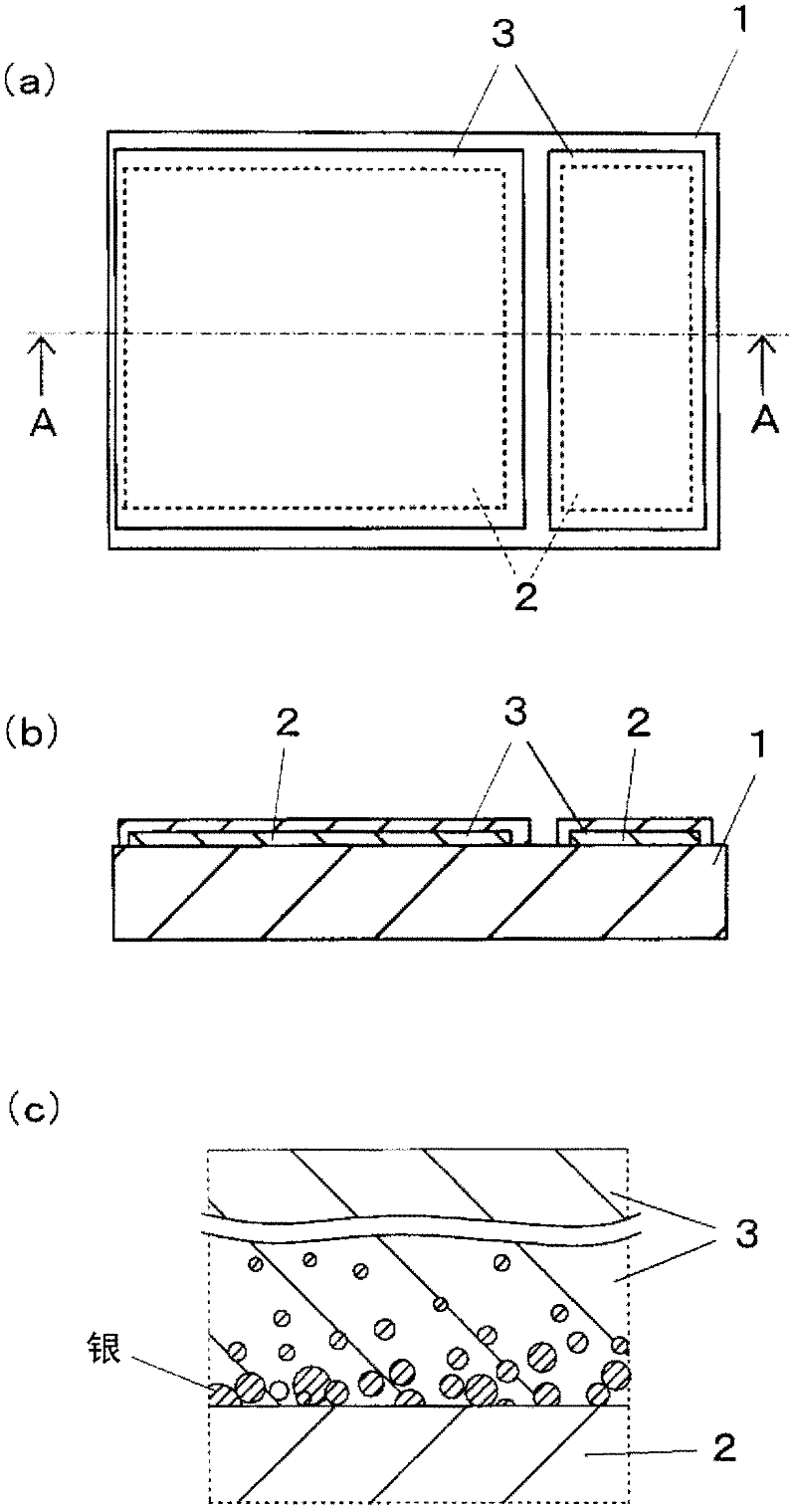
[0051] The light-reflecting substrate, the substrate for mounting a light-emitting element, and the light-emitting device of the present invention will be described with reference to the drawings. In addition, in the following description, the reflectance of light (visible light) may be simply called reflectance.

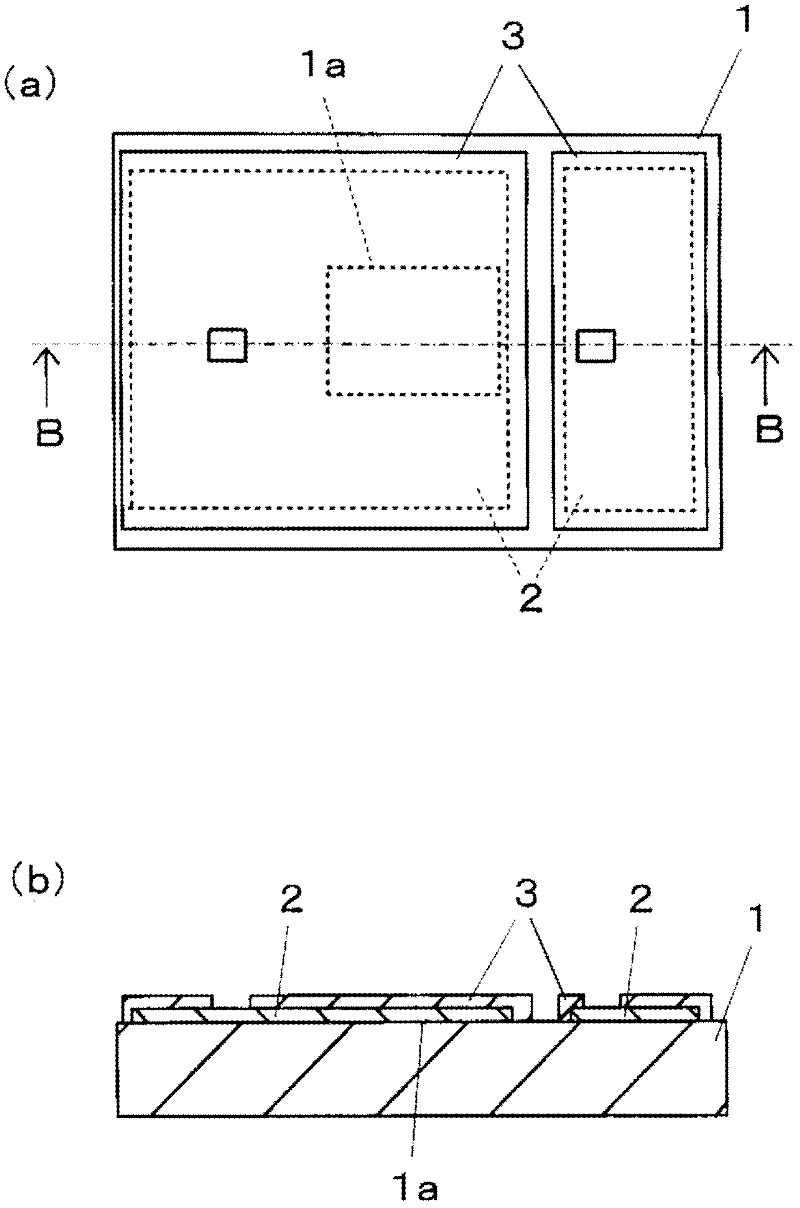
[0052] figure 1 (a) is a plan view showing an example of an embodiment of the light reflective substrate of the present invention, figure 1 (b) is figure 1 A sectional view of line A-A of (a), figure 1 (c) is to figure 1 The main part of (b) is further enlarged and a cross-sectional view schematically shown. The metal layer 2 adhered to the main surface (upper surface) of the insulating substrate 1 is covered with the glass layer 3, basically forming a light reflection substrate.

[0053] The light-reflecting substrate 1 is used in various applications for reflecting light, such as a substrate for mounting a light-emitting element for mounting a light-emitting ...


PUM


Abstract

Disclosed is a process for producing a substrate (9) which can be mounted in a light-emitting element, which comprises the steps of: applying a glass paste (33) comprising a powder of a glass material having a softening point that is higher than that of a glass component contained in a glass ceramic green sheet (11) and is lower than the melting point of silver onto silver or a conductive paste (22) mainly composed of silver which has been applied on the main surface of the glass ceramic green sheet (11), in such a manner that the silver or conductive paste (22) can be covered with the glass paste (33); and heating the resulting product to sinter the conductive paste (22) and also melt the glass paste (33), and then cooling the molten glass paste (33) to produce a transparent glass layer (3) that covers a metal layer (2) that has been formed by the sintering of the conductive paste (22). The use of the glass paste (33) enables the prevention of the occurrence of the reaction between silver contained in the conductive paste (22) and the glass component contained in the glass paste (33) upon the heating. Therefore, in the substrate (9), the metal layer (2) can be covered with the glass layer (3) that has high transparency.

Description

technical field [0001] The present invention relates to a light-reflecting substrate having a metal layer for reflecting light, a light-emitting element mounting substrate for mounting light-emitting elements such as light-emitting diodes or semiconductor lasers produced using the light-reflecting substrate, and a light-emitting element mounting substrate mounted on a light-emitting element mounting substrate. A light-emitting device made of elements, and a method of manufacturing a substrate for mounting a light-emitting element. Background technique [0002] In recent years, light-emitting elements such as LEDs (light-emitting diodes) and LDs (semiconductor lasers) have been widely used as light sources in various fields such as lighting and backlighting of mobile phones and large LCD TVs. A light source using such a light-emitting element requires characteristics such as high reliability, high luminous effect, and low calorific value. In particular, it is required to be ...

Claims


Application Information

Patent Timeline
IPC IPC(8): H01L33/60
CPCH01L33/486H05K2201/10106H05K1/0306H01L33/60H05K2201/017H01L2224/73265H01L23/3677H01L2224/48227H01L2224/32225H01L24/73H01L2224/48091H01L2924/00H01L2924/00012H01L2924/00014H01L33/48
Inventor 绪方良吉
Owner KYOCERA CORP
Why Eureka
Try Eureka