Rotor type compressor

A compressor and rotor-type technology, applied in the field of rotor-type compressors, can solve problems such as thermal deformation, eccentric clearance effects, internal leakage, etc., and achieve the effects of reducing components, ensuring coaxiality, and ensuring clearances

Active Publication Date: 2012-05-30
SHANGHAI HITACHI ELECTRICAL APPLIANCES CO LTD
View PDF11 Cites 5 Cited by
  • Summary
  • Abstract
  • Description
  • Claims
  • Application Information

AI Technical Summary

Problems solved by technology

[0004] (1) Ordinary rotor compressors are mostly welded to the cylinder or the upper cylinder head. The heat of welding leads to thermal deformation, which has a certain impact on the coaxiality of the compressor.
[0005] (2) When assembling ordinary rotor compressors, the coaxiality between the stator and the upper cylinder head is not easy to ensure, and the gap between the stator and the rotor is uneven
[0006] (3) When the air intake connecting pipe is installed at the cylinder of the ordinary rotary compressor, it is easy to affect the eccentric clearance
[0007] (4) Ordinary rotor compressors, no matter how the intake connecting pipe and suction port are installed, or high-precision processing, there will always be hidden dangers of internal leakage, such as figure 1 As shown, the inside of the compressor is high pressure, and the inside of the cylinder 6 is low pressure. Since there is a gap between the upper cylinder head 14, the cylinder 6 and the compressor housing 13, there is a large pressure difference between the high pressure gas and the low pressure gas in the cylinder, and the intake air If the seal between the connecting pipe 10 and the suction port 11 is not good, the high-pressure gas will directly enter the suction port from the gap, which seriously affects the efficiency of the compressor.

Method used


Image

  • Rotor type compressor
  • Rotor type compressor
  • Rotor type compressor

Examples


Embodiment 1

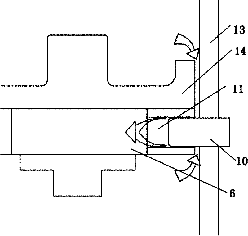
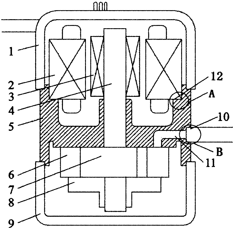
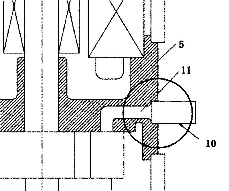
[0030] Such as Figure 1-2 As shown in the figure, the DC variable frequency rotary compressor using environmentally friendly refrigerant includes an upper casing cover 1, a stator 2, a rotor 3, a crankshaft 4, an upper cylinder head and a casing combined into one, and a one-piece frame 5 , cylinder 6, piston 7, lower cylinder head 8, lower shell cover 9, intake connecting pipe 10, integrated frame 5 is made of metal material, such as cast iron (FC250) by casting one-time molding. The upper part of the integrated frame 5 is connected and fixed with the upper case cover 1 by laser welding, and the lower part is connected and fixed with the lower case cover 9, as figure 1 As shown in A, the top of the integrated frame 5 is provided with an inner concave platform, and the inner concave platform is provided with an inner concave platform plane 12, and the lower end of the stator 2 is fixedly connected to the inner concave platform plane 12 by bolts. The stator is installed on thi...

Embodiment 2

[0035] see Figure 1-2 As shown, a rotor compressor, wherein the stator is directly connected to the stepped plane on the inner concave platform plane 12 of the integrated frame 5 through bolts. The top of the integrated frame 5 is connected and fixed with the upper shell cover 1 by glue, and its bottom is connected and fixed with the lower shell cover 9 with glue, and all the other structures are the same as in Embodiment 1.


PUM


Abstract

The invention relates to a rotor type compressor, which comprises: an upper shell cover, stators, rotors, a crankshaft, a shell, an upper cylinder cover, a cylinder, a piston, blades, a lower cylinder cover, a lower shell cover, and an air inlet connecting pipe. The upper cylinder cover and the shell are integrated together and molded into a one-piece frame in one step. The top of the one-piece frame is provided with a concave platform that is equipped with a concave platform plane, on which the lower ends of the stators are fixed. The one-piece frame is provided with an air suction port, one end of which is disposed on a side of the one-piece frame and the other end of which is disposed on a contact surface between the one-piece frame and the cylinder. The air inlet connecting pipe is introduced into the air suction port under static pressure so as to be in interference fit with the air suction port. Compared with prior art, the compressor of the invention has the advantages of coaxiality, uniform gap between the stators and rotors, no influence on the eccentric gap of a pump body during installing the air inlet connecting pipe, and no hidden trouble of internal leakage, etc.

Description

technical field [0001] The present invention relates to a rotary compressor, in particular to a rotary compressor. Background technique [0002] The current assembly method of ordinary rotor compressors is: the compressor pump body is assembled separately, then the rotor is cold pressed or shrunk on, the pump body and stator are assembled using a gap gauge, and then the casing is shrunk on, and the intake connection is installed. tube, then weld the upper cylinder head or cylinder, and finally weld the upper and lower shell covers and the liquid reservoir. [0003] The main problems of the structure of this common rotary compressor are as follows: [0004] (1) Ordinary rotor compressors are mostly welded to the cylinder or the upper cylinder head. The heat of welding leads to thermal deformation, which has a certain impact on the coaxiality of the compressor. [0005] (2) When the ordinary rotor compressor is assembled, the concentricity between the stator and the upper cy...

Claims


Application Information

Patent Timeline
Patent Type & Authority Applications(China)
IPC IPC(8): F04C29/00
Inventor 沈建芳刘寅俊张龙周韬
Owner SHANGHAI HITACHI ELECTRICAL APPLIANCES CO LTD
Why Eureka
Try Eureka