Cascading LED driving circuit

A technology of light-emitting diodes and driving circuits, which is applied in the layout of electric lamp circuits, light sources, electric light sources, etc., can solve the problems of high production cost, complicated circuits, and energy waste.

Active Publication Date: 2012-05-30
IML HONG KONG LTD
View PDF4 Cites 9 Cited by
  • Summary
  • Abstract
  • Description
  • Claims
  • Application Information

AI Technical Summary

Problems solved by technology

[0011] Although the above-mentioned LED controller can improve energy utilization efficiency, the circuit is too complicated and the ...

Method used


Image

  • Cascading LED driving circuit
  • Cascading LED driving circuit
  • Cascading LED driving circuit

Examples


Embodiment Construction

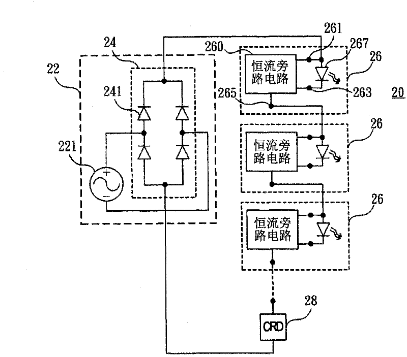
[0042] First, see figure 2 , figure 2 is a schematic circuit diagram of a preferred embodiment of the present invention. As shown in the figure, the cascaded LED driving circuit 20 of this embodiment mainly includes a power module 22 , a plurality of LED modules 26 and a constant current component 28 .

[0043] Wherein, the power module 22 is mainly used to provide a DC voltage and a ground potential, which can be provided by an AC power source 221 plus a rectification unit 24 . The rectification unit 24 is preferably a bridge rectifier composed of diodes 241 .

[0044]Each LED module 26 includes a constant current bypass circuit 260 and a LED 267 respectively. In each LED module 26, the constant current bypass circuit 260 has a first terminal 261, a second terminal 263 and a third terminal 265, and the LED 267 is connected between the first terminal 261 and the second terminal 263 .

[0045] The DC voltage or the output voltage of the LED module 26 of the upper stage i...


PUM


Abstract

The invention relates to a cascading LED driving circuit which can lighten different quantities of the LEDs according to voltage variation. By using the cascading LED driving circuit, efficiency can be improved. The circuit mainly comprises: a power supply module, a plurality of LED modules and a constant current assembly. The each LED module comprises: a constant current bypass circuit and at least one LED. The LED is connected in series between a first terminal and a second terminal of the constant current bypass circuit. The first terminal of the each constant current bypass circuit is connected with the power supply module or a third terminal of a higher-level constant current bypass circuit and is connected in series with the constant current assembly in the circuit. Therefore, different quantities of the LEDs can be lightened according to the different voltages and the energy usage efficiency can be improved.

Description

technical field [0001] The invention relates to a cascaded light-emitting diode drive circuit, especially a cascaded light-emitting diode drive circuit that can light up different numbers of light-emitting diodes according to voltage changes and can improve efficiency. Background technique [0002] see figure 1 , figure 1 It is a schematic diagram of an existing light-emitting diode (LED) driving circuit. In order to reduce the size of the circuit and save costs, some manufacturers use transistors to control the conduction of the circuit in a specific voltage range, thereby omitting bulky components such as transformers and filter capacitors. [0003] The LED driving circuit 10 mainly rectifies an AC power source 12 with a bridge rectifier 14 including a plurality of diodes 141 to form a DC power source. In the LED drive circuit 10, an N-type metal oxide half-power transistor 16 is used to control the conduction and closure of the current, a first transistor 151 is used t...

Claims


Application Information

Patent Timeline
IPC IPC(8): H05B37/02
Inventor 陈德铮
Owner IML HONG KONG LTD
Why Eureka
Try Eureka