

Wheel support structure for two-wheeled vehicle
A technology for motorized two-wheeled vehicles and wheels, which is applied to motor vehicles, bearings for rotational motion, wheels, etc., can solve the problems of wheel support structure cost reduction, required processing time, and complicated procedures, so as to improve reliability and prevent creep The effect of changing and simplifying the process
- Summary
- Abstract
- Description
- Claims
- Application Information
AI Technical Summary
Problems solved by technology
Method used
Image

Examples
Embodiment Construction
[0087] Hereinafter, embodiments of the wheel support structure for a motorcycle according to the present invention will be described in detail with reference to the drawings. The basic shape, size, and material of each component constituting the wheel support structure of the present invention are the same as those used in conventional wheel support structures for motorcycles, unless otherwise specified. Therefore, only the characteristic parts of each embodiment of the present invention will be described in detail, and the description of the same parts as conventional structures will be simplified or omitted. In addition, description of common parts between the embodiments is also simplified or omitted.
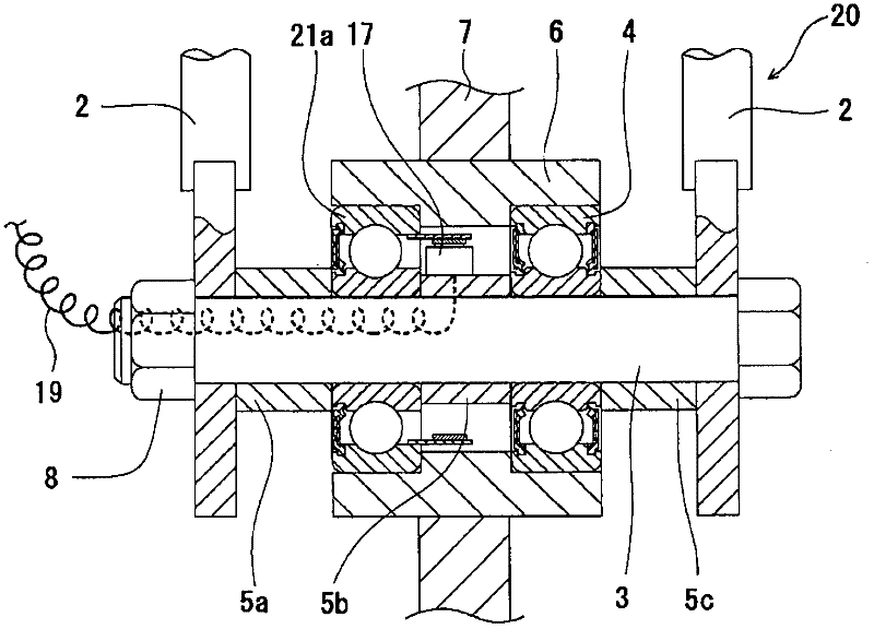
[0088] figure 1 An example of the wheel support structure of the motorcycle capable of detecting the rotational speed of the wheel according to the first aspect of the present invention is shown. The wheel support structure 20 replaces, for example, the Figure 35 One of ...
PUM
 Abstract
Description
Claims
Application Information