
Arrangement having an electric machine and method for operating an electric machine

A thermopile and rotor technology, applied in electromechanical devices, measuring devices, electric components, etc., can solve the problems of temperature detection distortion, measurement distortion, impossible multiple positions of the structure, etc.

Inactive Publication Date: 2012-05-30
SIEMENS AG
View PDF5 Cites 14 Cited by
  • Summary
  • Abstract
  • Description
  • Claims
  • Application Information

AI Technical Summary

Problems solved by technology

[0004] This device has the disadvantage that the radial openings ("perforations") in the stator of the electrical machine can only be realized with great difficulty due to the windings arranged there and especially in complex electrical machines, or for structural reasons in many position is impossible and often even completely impossible
Furthermore, due to the distance between the external infrared temperature sensor and the outer surface of the rotor, the mentioned optical system, namely the lens system, is required, which increases the cost of the device
Finally, the "channels" designed for temperature detection, i.e. the substantially radial openings in the motor's stator, can deposit dust particles over time distorting or making temperature detection impossible
[0005] Another problem is reflections especially in the interior of the channel and due to the radiation of the stator's own heat in this area, which can further distort the measurement
In particular larger electrical machines in some cases have cooling air openings which are suitably formed radially with respect to the rotor, whereas especially in medium and small electrical machines such openings are usually not possible or are not possible at all for space reasons

Method used


Image

  • Arrangement having an electric machine and method for operating an electric machine
  • Arrangement having an electric machine and method for operating an electric machine
  • Arrangement having an electric machine and method for operating an electric machine

Examples


Embodiment Construction

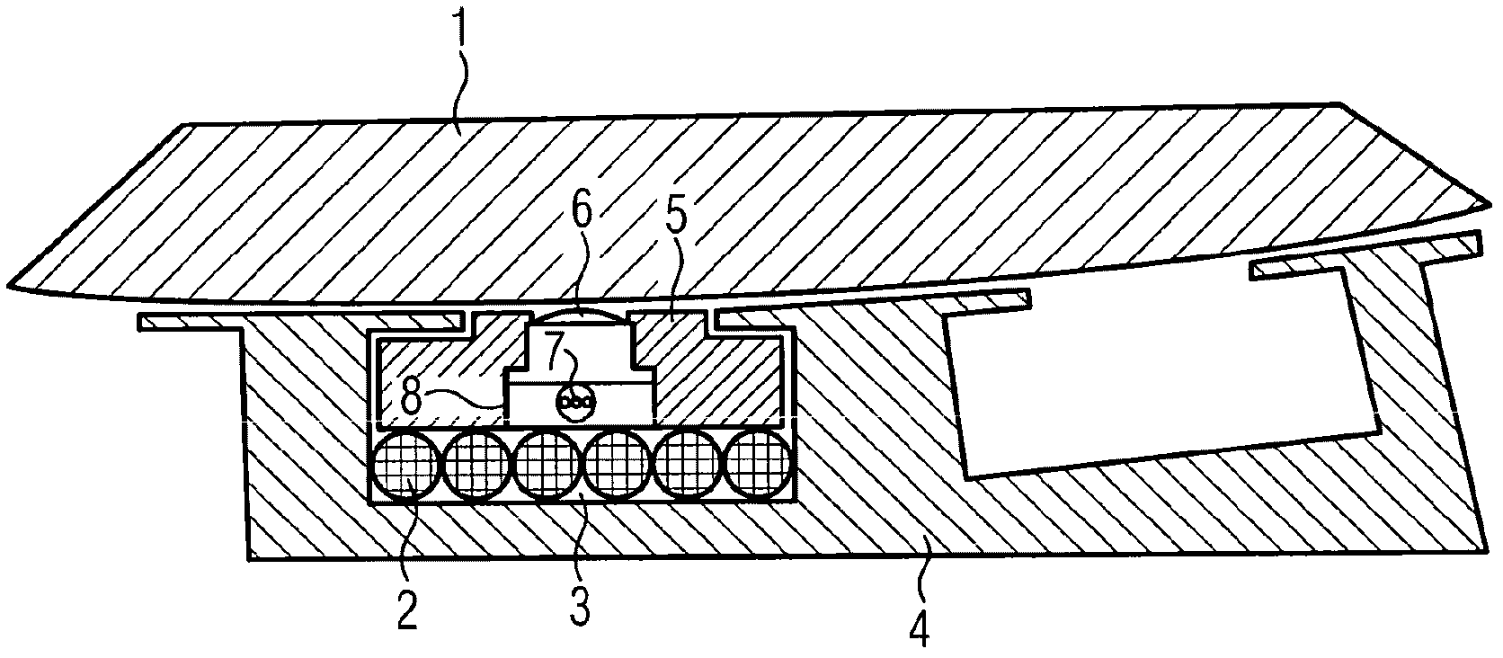
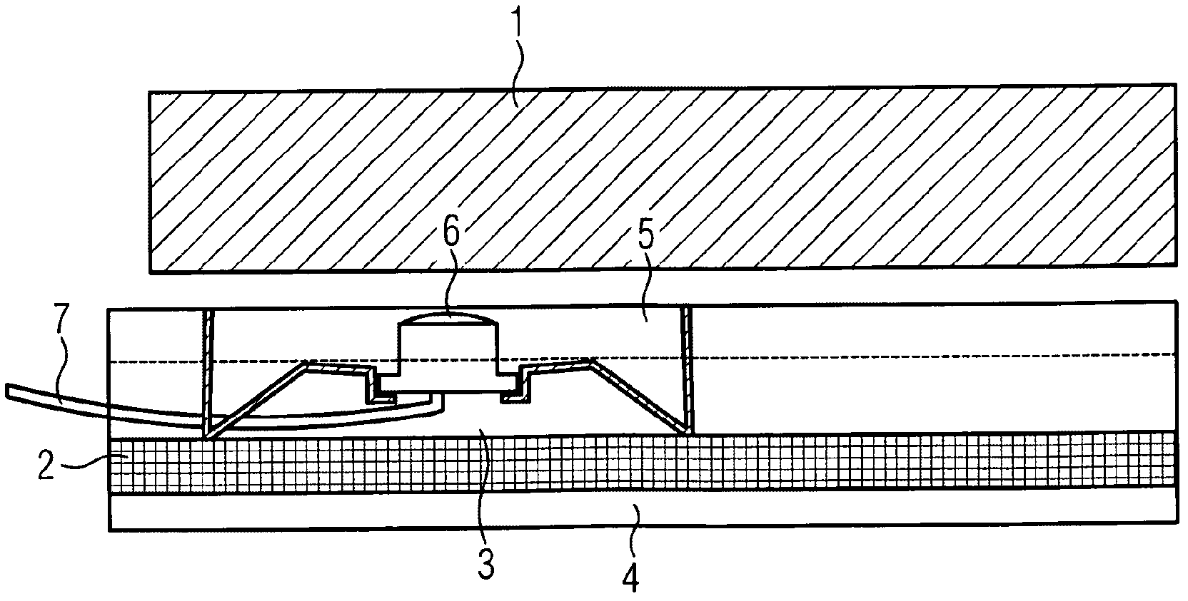
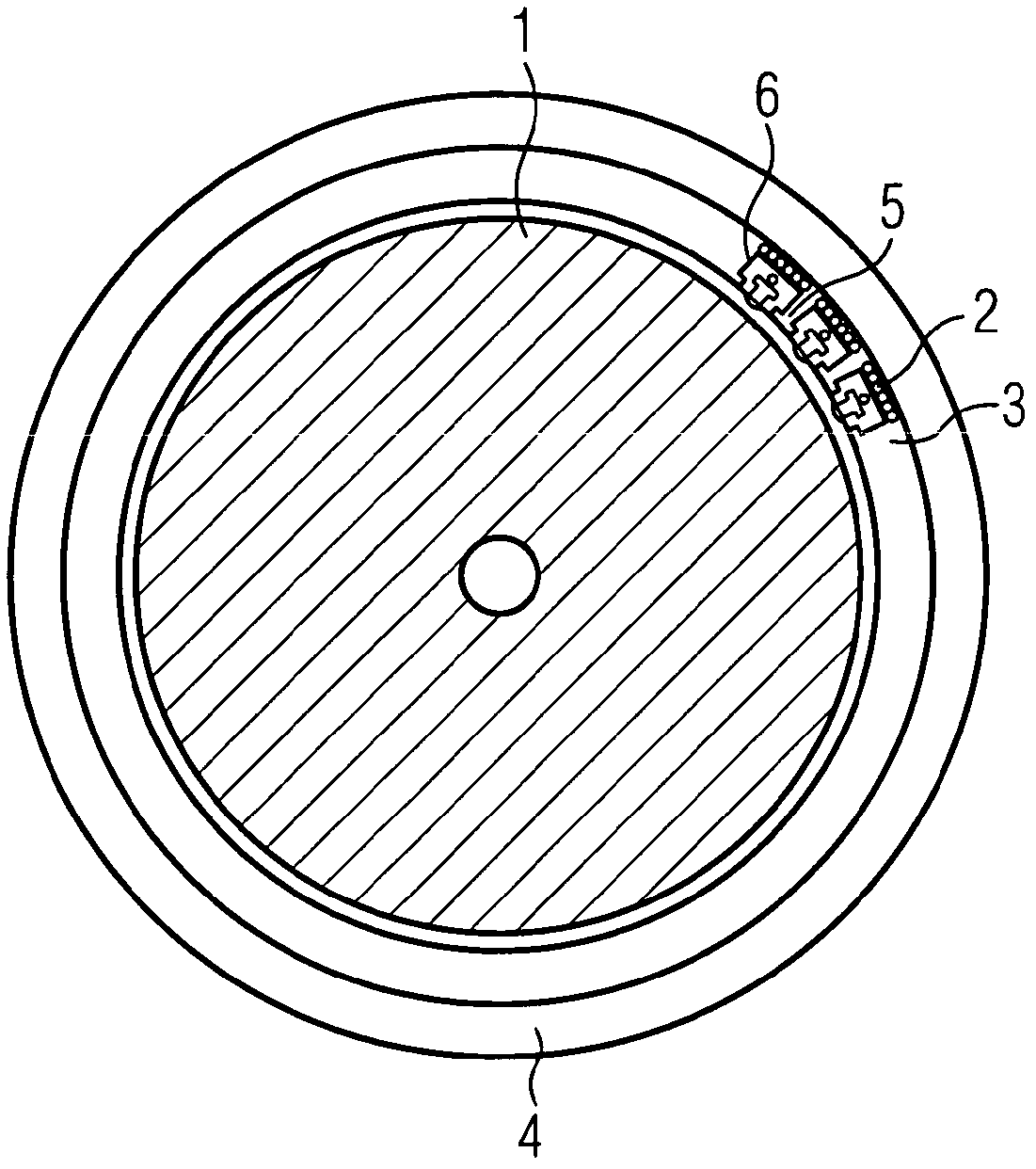
[0021] exist figure 1 A schematic sectional view (cross section) of a section of an electric machine with rotor 1 and stator 4 is shown in . A slot 3 is provided in the stator, in which slot the winding 2 of the stator 4 runs. For clear reasons, in figure 1Only 6 coil layers with winding 2 are shown in . In the slot closing wedge 5 of the slot 3 is introduced a deep hole 8 which is completely filled with a thermopile 6 (infrared temperature sensor). The deep hole 8 has a through-opening at the rotor 1, into which the detection side of the thermopile 6 protrudes, wherein on this side the side of the thermopile 6 consists of a transparent plastic which Has a lens-shaped surface. Since the through holes have a smaller diameter than the deep holes, the deep holes 8 are provided with a depth limit that prevents the thermopile 6 from falling into the air gap between the rotor 1 and the stator 4 . The thermopile 6 rests firmly against the winding 2 on the winding 2 , so that it ...


PUM


Abstract

The invention relates to a method and arrangement having an electric machine, comprising a stator (4) and a rotor (1) and an infrared temperature sensor, wherein the detection field of the infrared temperature sensor is directed at an outer surface of the rotor (1). The infrared temperature sensor is a thermopile (6) for radiometrically contactlessly detecting a temperature of the rotor (1), the thermopile being arranged in a slot of the stator (4) and being compatible with standard slot-sealing-wedge components of the electric machine with regard to assembly, and thus enables the operational monitoring of the thermal state of an electric machine in a novel manner, such that adapted power states can be achieved.

Description

technical field [0001] The invention relates to a device with an electric motor according to the preamble of claim 1 and a method for driving an electric motor according to claim 9 . Background technique [0002] In installations with complex installation situations and in extreme ambient conditions, temperature measurement with contact thermometers is generally not possible. Especially in electric machines, ie in electric motors and generators, temperature measurement on rotating parts is a practical problem. It is therefore desirable, for example, to monitor the temperature of the armature, ie the rotor, of electric motors and generators, since such monitoring allows conclusions to be drawn on the operating state of the electric machine and enables design optimization of the power class of the electric motor. In this way, in particular the often occurring overdimensioning of the motor can be avoided in order to also prevent overheating of the permanent magnets which demag...

Claims


Application Information

Patent Timeline
Patent Type & Authority Applications(China)
IPC IPC(8): G01J5/00G01J5/04H02K11/00
CPCG01J5/00G01J5/044H02K11/0047G01J5/0022G01J5/0096G01J5/042G01J5/048G01J5/04H02K11/25
Inventor 于尔根·策特纳
Owner SIEMENS AG
Learn More