Optical temperature sensor

A fiber optic temperature and sensor technology, applied in thermometers, instruments, optics, etc., can solve the problems of high grating price and complicated equipment, and achieve the effect of reducing setting space, reducing constraints, and simple structure

Inactive Publication Date: 2012-05-30
OPTO POWER
View PDF5 Cites 6 Cited by
  • Summary
  • Abstract
  • Description
  • Claims
  • Application Information

AI Technical Summary

Problems solved by technology

[0007] However, it is expensive to write a grating on an optical fiber, and since the temperature is calculated by detecting the change of the peak wavelength, the equipment required to calculate the temperature is very complicated.

Method used


Image

  • Optical temperature sensor
  • Optical temperature sensor
  • Optical temperature sensor

Examples


Embodiment Construction

[0050] Hereinafter, the optical fiber temperature sensor of the preferred embodiment of the present invention will be described in more detail with reference to the accompanying drawings.

[0051] First, an optical fiber temperature sensor according to a first embodiment of the present invention will be described.

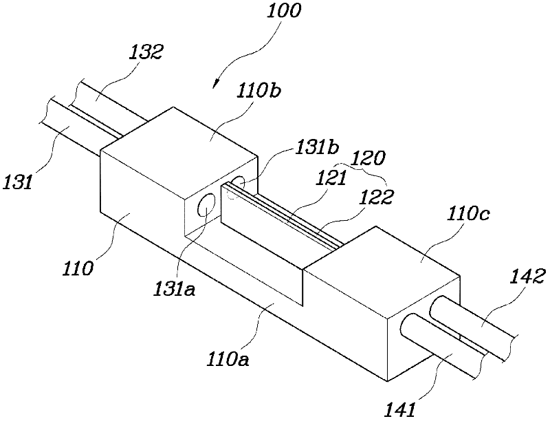
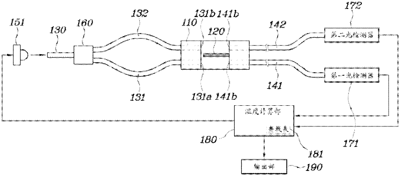
[0052] figure 1 It is a perspective view of the optical fiber temperature sensor of the present invention. figure 2 for figure 1 The circuit diagram of the control system of the fiber optic temperature sensor.

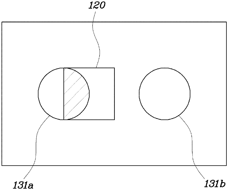
[0053] Such as figure 1 and figure 2 As shown, the fiber optic temperature sensor 100 includes: a housing 110, a bimetal element 120, a light source 151, an optical splitter 160, a first input fiber 131 and a second input fiber 132, a first output fiber 141 and a second output The end optical fiber 142 , the first photodetector 171 and the second photodetector 172 , and the temperature calculation unit 180 .

[0054] The housing 110 has a structure ...


PUM


Abstract

The present invention relates to an optical temperature sensor, comprising: a housing; a light-transmitting unit, installed in the housing, for emitting light transmitted through an optical fiber into an inner space of the housing; and a bimetal device, movably installed in the housing, for varying the amount of transmitted light, wherein the optical temperature sensor is capable of measuring a temperature by using the amount of light, from the light transmitted via the optical fiber, which is shielded through bending due to a change in the temperature of the bimetal device, or using the amount of light, from the transmitted light, which is reflected and received. The optical temperature sensor has a simple structure and is not particularly restricted in terms of installation space.

Description

technical field [0001] The present invention relates to an optical fiber temperature sensor. Specifically, the optical fiber temperature sensor detects the amount of received light that changes with the operation of a bimetallic element whose operation changes with the temperature, and measures temperature. Background technique [0002] Various sensors for measuring temperature are known, and recently, a structure capable of measuring the temperature of a facility to be monitored remotely by using an optical fiber has been provided. [0003] An optical fiber temperature sensor associated with the present invention is disclosed in Japanese Laid-Open No. 55-080021. In the optical fiber temperature sensor, a light beam is emitted from the optical fiber at the input end, and as the temperature changes, the bimetal vertically arranged relative to the light beam covers the light beam, and the optical fiber at the output end detects the light beam and senses the temperature change....

Claims


Application Information

Patent Timeline
Patent Type & Authority Applications(China)
IPC IPC(8): G01K11/32G01K11/12G02B6/00
CPCG01K11/3206G02B6/2817G01K5/62
Inventor 金永洙
Owner OPTO POWER
Why Eureka
Try Eureka