
Vehicle having at least one cooling circuit for cooling a fuel cell system

A fuel cell system and cooling circuit technology, applied in fuel cells, fuel cell additives, transportation fuel cell technology, etc., can solve problems such as performance degradation, high energy consumption, and fuel cell stack cooling deterioration.

Inactive Publication Date: 2012-05-30
DAIMLER AG
View PDF8 Cites 8 Cited by
  • Summary
  • Abstract
  • Description
  • Claims
  • Application Information

AI Technical Summary

Problems solved by technology

[0010] With such a combination, when using the air conditioning system to cool the interior of the vehicle, there is always the disadvantage that the heat entering the cooling circuit is further increased, so that especially at very high ambient temperatures, the fuel cell stack cooling will further deteriorate
Due to this deterioration in fuel cell cooling, the performance of a vehicle equipped with a fuel cell system is correspondingly reduced
The assisted cooling of the fuel cell cooling circuit described in US 6,370,903 B1 by means of the evaporator of the air conditioner has the disadvantage that such a cooling is accompanied by a relatively high energy consumption in the air conditioner, so that such Equipped cars have a reduced overall efficiency rating

Method used


Image

  • Vehicle having at least one cooling circuit for cooling a fuel cell system
  • Vehicle having at least one cooling circuit for cooling a fuel cell system
  • Vehicle having at least one cooling circuit for cooling a fuel cell system

Examples


Embodiment Construction

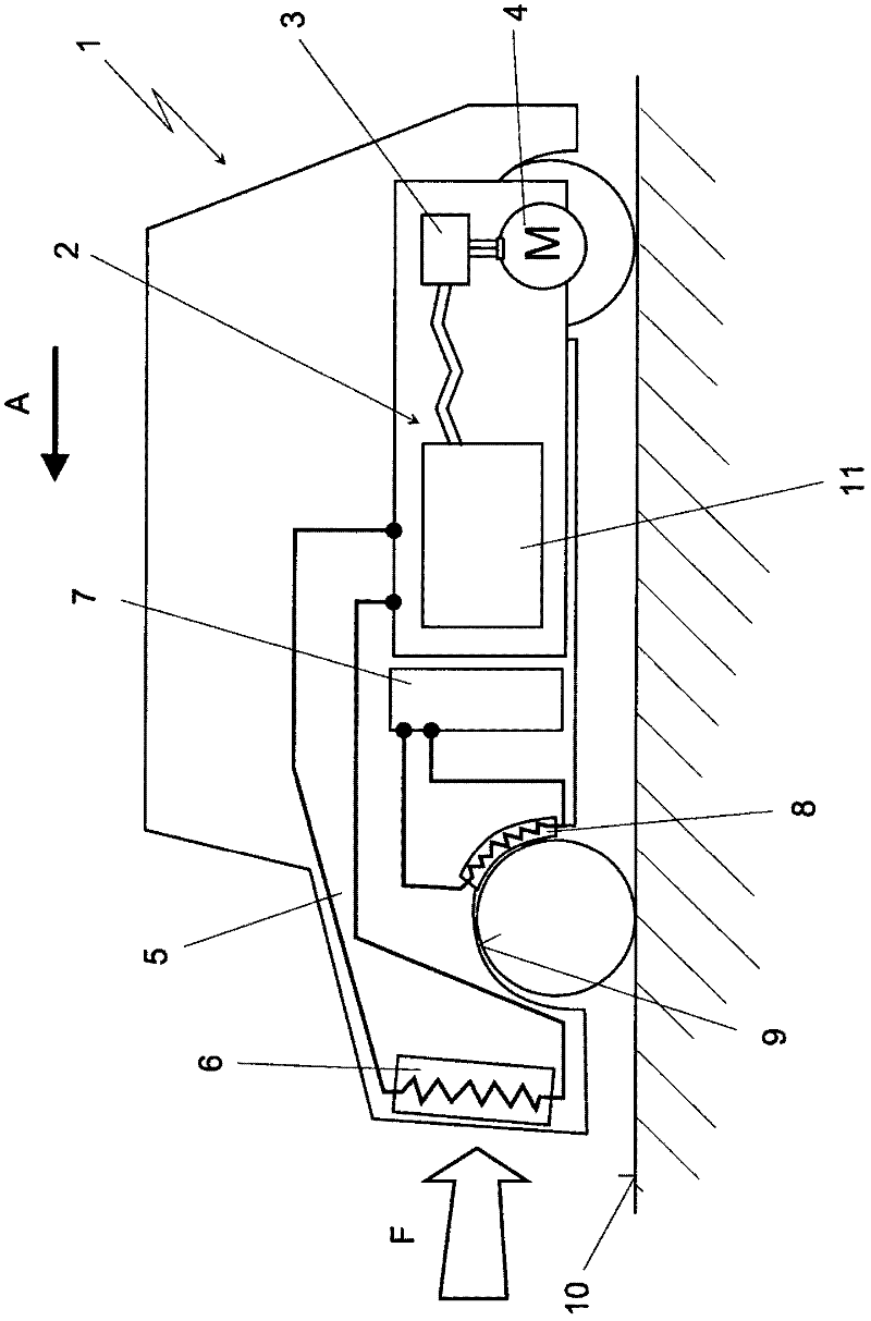
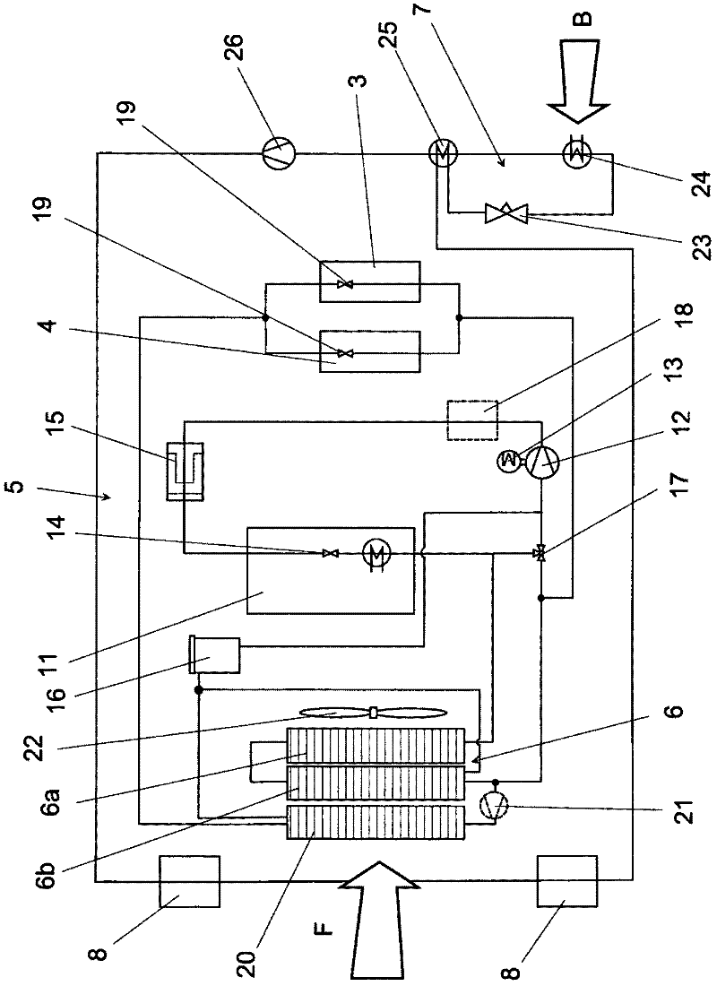
[0021] figure 1 As an example, a motor vehicle 1 is shown, comprising a fuel cell system 2 via which the motor vehicle 1 is supplied with electrical drive power. The motor vehicle 1 is driven via a corresponding electronic system 3 and an electric drive in the form of an electric motor 4 , which can in particular also be a motor or, in the known manner, a generator during braking of the motor vehicle. The fuel cell system 2 here has at least one cooling circuit, which is denoted here, for example, by line 5 . Part of the cooling circuit 5 is a cooling heat exchanger 6 which is arranged in the front end region of the motor vehicle 1 , ie in the direction of travel A ahead. The movement-related air flow F, which generates a corresponding dynamic pressure in the front end region of the motor vehicle 1 in a known manner, flows through the cooling heat exchanger 6 and thus has a positive effect on the cooling medium circulating in the cooling circuit 5—typically Ground is a water...


PUM


Abstract

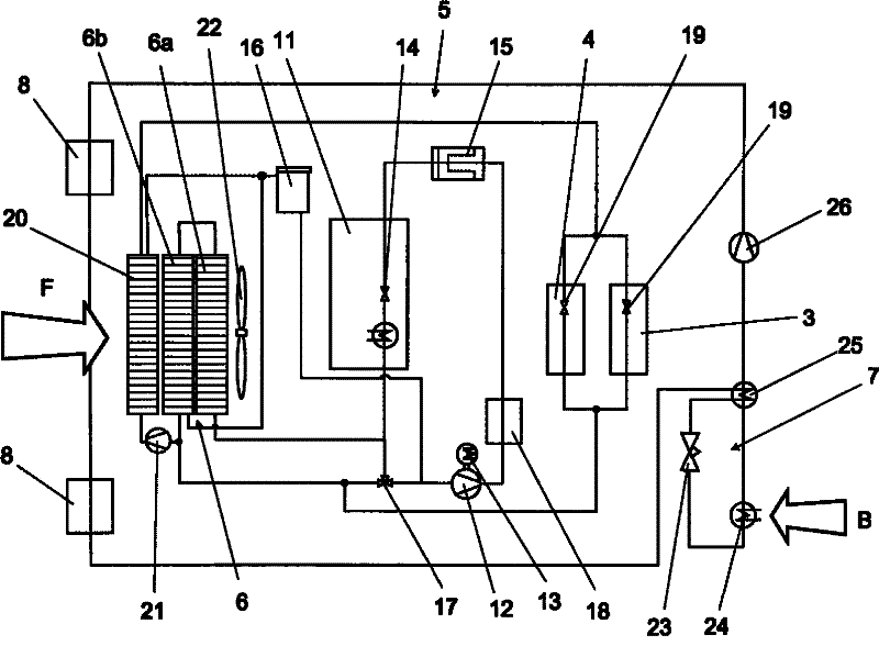
The invention relates to a vehicle, comprising at least one cooling circuit (5) for cooling a fuel cell system (2). The cooling circuit (5) comprises at least one cooling heat exchanger (6), a coolant conveying device (12), and a heat exchanger in a fuel cell stack (11) of the fuel cell system (2). The airstream (F) flows against on the cooling heat exchanger (6) as cooling air. According to the invention, the cooling heat exchanger (6) has at least two stages (6a, 6b), which are designed in such a way that the relative wind (F) flows through the two stages consecutively in series.

Description

technical field [0001] The invention relates to a motor vehicle of the type specified in the preamble of claim 1 having at least one cooling circuit for cooling a fuel cell system. Background technique [0002] A fuel cell system for vehicles of the general type is known from DE 196 29 048 C2. The fuel cell system includes a main cooling heat exchanger, similar to the structure in a car with an internal combustion engine, so configured that the dynamic pressure against the wind during driving ensures the circulation of ambient air as cooling air. In order to utilize the dynamic pressure, essentially only the front surface of the vehicle is available for the cooling heat exchanger. However, there are corresponding limitations and disadvantages, and these and other problems will be described together below. [0003] For PEM fuel cell applications, the heat dissipation of the fuel cell drive system during operation becomes a problem and limits the performance, since most of t...

Claims


Application Information

Patent Timeline
Patent Type & Authority Applications(China)
IPC IPC(8): H01M8/04B60H1/00B60K11/04B60L11/18F28D1/00
CPCY02T90/34H01M2008/1095H01M2250/20Y02T90/32H01M8/04059B60H1/00207F28D1/0435B60L11/1892Y02E60/50B60L11/1881H01M8/04029B60H1/00357B60L58/30B60L58/33Y02T90/40
Inventor R·霍斯
Owner DAIMLER AG
Learn More