Built-in magnetic separation filter pressing dehydrator
A technology of magnetic separation and press filtration dehydration, which is applied in magnetic separation, press, solid separation, etc.
- Summary
- Abstract
- Description
- Claims
- Application Information
AI Technical Summary
Problems solved by technology
Method used
Image
Examples
Embodiment 1
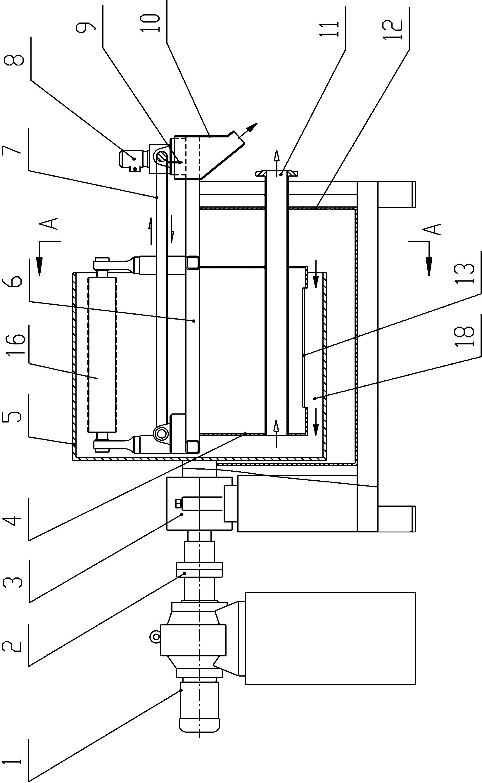
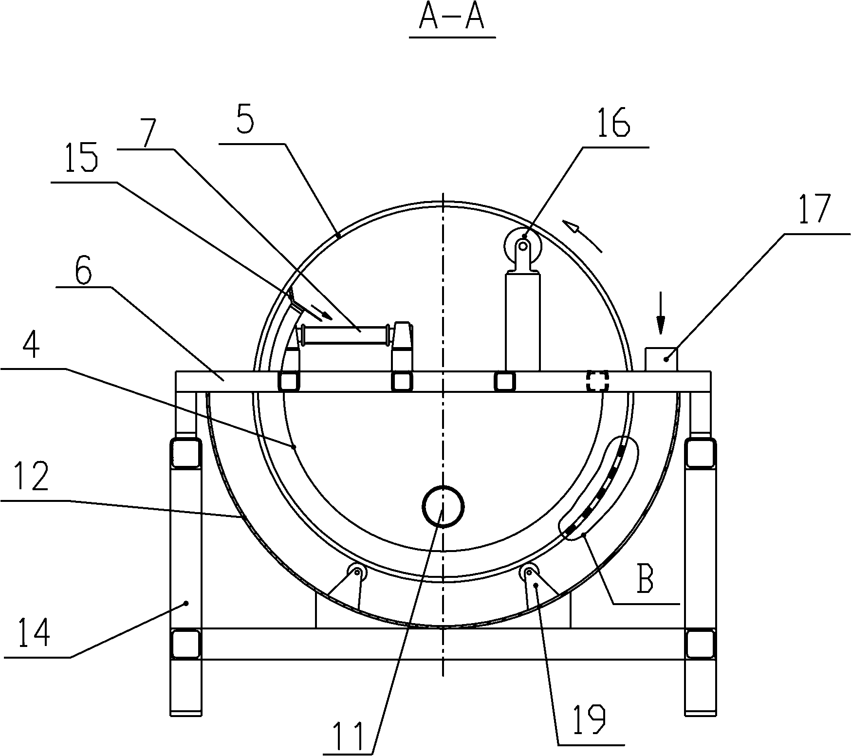
[0030] combine figure 1 , figure 2 As shown, a built-in magnetic separation filter press dehydrator is used to separate and dehydrate magnetic slag water, including a frame 14, a cantilever bracket 6 arranged on the frame 14, a motor reducer 1, and a coupling 2. Bearing seat 3, outer groove 12, magnetic cylinder 5, feed port 17, drain pipe 11, magnetic cylinder 5 is located in outer groove 12, the supporting end shaft of magnetic cylinder 5 passes through outer groove 12 and one end is supported by bearing seat 3 It is driven to rotate by the motor reducer 1 through the coupling 2; an inner groove 4 is arranged on the inner lower part of the magnetic cylinder 5, and the upper edge of the inner groove 4 is fixed on the cantilever bracket 6; a pressure roller 16 is built in the inner upper part of the magnetic cylinder 5 and The inner cylinder of the magnetic cylinder 5 cooperates to press the slag; that is, the magnetic slag is magnetically adsorbed on the inner cylinder 5.2 ...
Embodiment 2
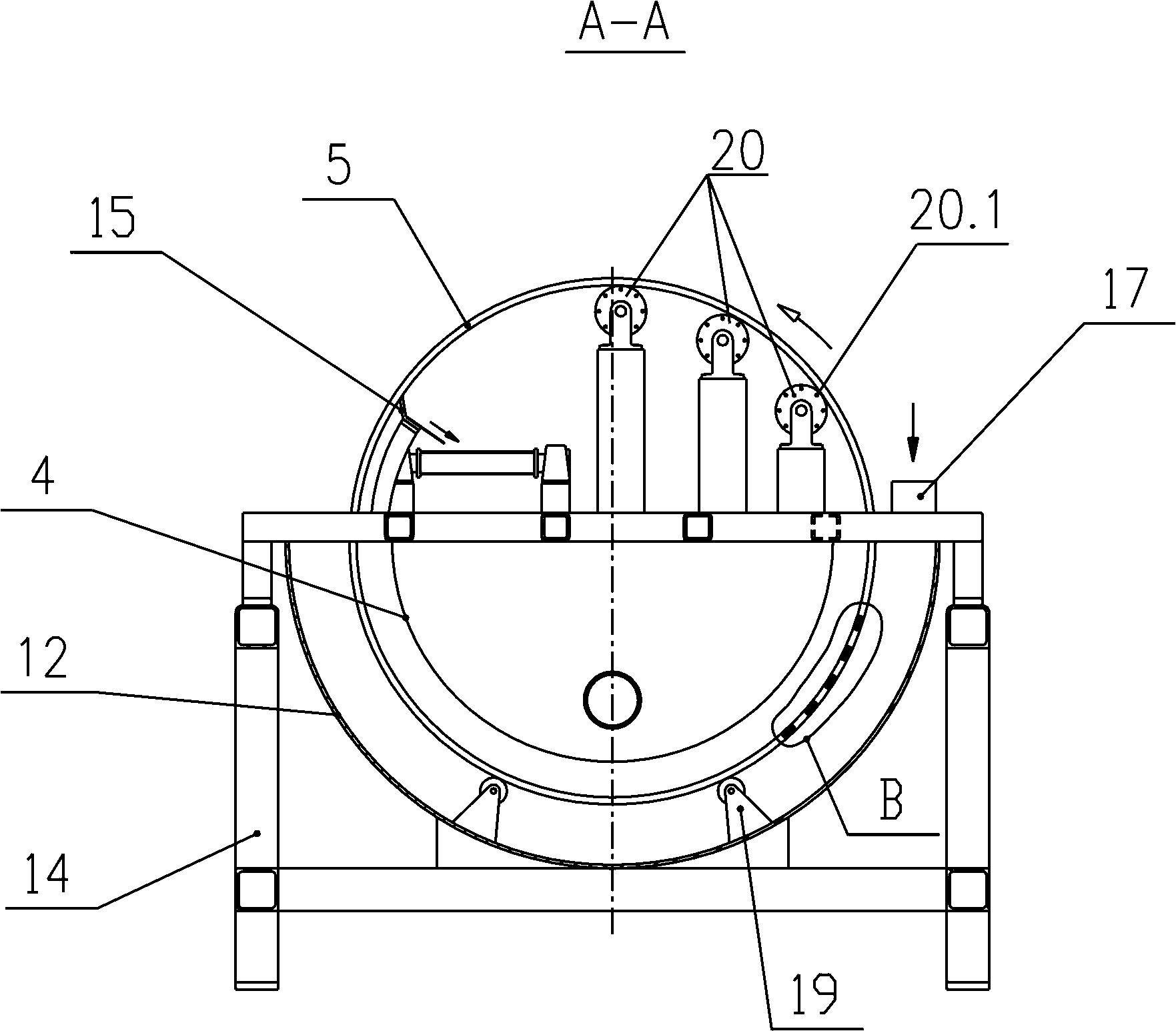
[0032] In combination with Example 1, such as image 3 As shown, in order to further improve the effect of pressing and dehydrating, we designed the press roller 16 as a filter cartridge 20 with a filtering function. During the pressing and dehydrating process of the filter cartridge 20, a part of the water flows down the outer wall of the filter cartridge 20 to the inner tank. The other part of water enters the filter cartridge 20 through the filter layer of the filter cartridge 20 and falls from the water filter holes 20.1 provided on both ends of the filter cartridge 20 to the inner tank 4, and finally flows into the magnetic separation flow channel 18 through the slag opening 13 of the inner tank to realize Further separation and dehydration.
Embodiment 3
[0034] In combination with embodiment 1 and embodiment 2, such as image 3As shown, three filter cartridges 16 are arranged in the same magnetic cylinder 5, so that the moisture in the dried slag can be compressed step by step on one magnetic cylinder 5, so that the moisture content of the slag is very low. When the equipment is running, the magnetic slag water or magnetic material enters the outer tank 12 from the feed port 17, and then enters the magnetic separation flow channel 18. The magnetic slag material is adsorbed on the inner surface of the magnetic cylinder by the magnetic field of the inner cylindrical surface 5.2 of the magnetic cylinder. The water enters the drain pipe 11; the slag adsorbed on the inner surface of the magnetic cylinder moves out of the liquid surface with the rotation of the magnetic cylinder 5, and is squeezed out by the filter cylinder 16 step by step. The slag conveying belt 7 is output. During this process, the slag conveying belt 7 is driven...
PUM
 Abstract
Description
Claims
Application Information
 - R&D
- Intellectual Property
- Life Sciences
- Materials
- Tech Scout
- Unparalleled Data Quality
- Higher Quality Content
- 60% Fewer Hallucinations
Browse by: Latest US Patents, China's latest patents, Technical Efficacy Thesaurus, Application Domain, Technology Topic, Popular Technical Reports.
© 2025 PatSnap. All rights reserved.Legal|Privacy policy|Modern Slavery Act Transparency Statement|Sitemap|About US| Contact US: help@patsnap.com


