Automatic butt welding method and equipment

A touch welding, automatic technology, applied in welding equipment, resistance welding equipment, metal processing equipment, etc., can solve the problems of different lengths of high-current wires, difficult to handle the shape of the wire to be welded, etc. , the effect of small footprint

Active Publication Date: 2013-10-09
ELRAD ELECTRONICS DONGGUAN
View PDF8 Cites 0 Cited by
  • Summary
  • Abstract
  • Description
  • Claims
  • Application Information

AI Technical Summary

Problems solved by technology

[0005] In order to solve the problems of different lengths of high-current wires and difficulty in processing the shape of the wire ends to be welded in the prior art, the present invention proposes an automatic butt welding method and equipment, which completely solves many disadvantages of the prior art

Method used


Image

  • Automatic butt welding method and equipment
  • Automatic butt welding method and equipment

Examples


Embodiment Construction

[0036] The present invention will be described in further detail below in conjunction with preferred embodiment shown in accompanying drawing, as figure 1 , figure 2 Shown:

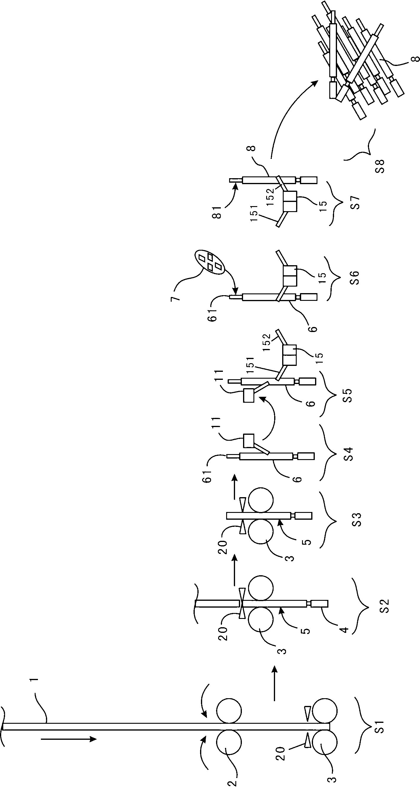
[0037] The system flow of an automatic butt welding method is as follows: figure 1 shown.

[0038] Implement a method for automatic butt welding, said method comprising the steps of:

[0039] S1). First, insert the end of the wire 1 into the first clamping rubber wheel set 2, turn on the power, and the intelligent control unit works;

[0040] The intelligent control unit drives the first wire clamping rubber wheel group 2 to rotate according to the set length of the front wire sheath 4, the stripping length, the target wire length, and the length of the remaining welding wire head 61;

[0041] When the thread head enters the clamping of the second clamping rubber wheel group 3, the cutting knife group 20 is located at the set length of the front thread sheath 4, the first thread clamping rubber wheel...


PUM


Abstract

The invention discloses an automatic butt welding method and automatic butt welding equipment. The equipment comprises an intelligent control unit for controlling a first split line rubber wheel group and a second split line rubber wheel group, and a cutting tool group which is driven by a cutting motor, wherein a single clamping device, a pair of clamping devices and a square butt welding groove are driven by the intelligent control unit. By the method and the equipment, a guiding wire can be cut into guiding wire sections to be used with consistent sizes in a full automatic mode, and the skin of a wire head at one end of a guiding wire section to be used can be stripped slightly in advance and is completely stripped in the official mounting process, so that wire heads are prevented from being scattered; and a wire head to be welded of the guiding wire section to be used can be prepared into a wire head with a square cross section in a full automatic mode, so that the wire heads in the form has small occupied space, are welded firmly and are standard and tidy when welded on welding points.

Description

technical field [0001] The invention relates to a wire processing method and equipment, in particular to a wire cutting and wire end processing method and equipment. Background technique [0002] When traditional electronic equipment is assembled, some thicker wires are required to conduct relatively large currents. The size and shape of these wires in the electronic equipment must be shaped according to the design. If the number of these wires is large, only relying on Manufacture such wires will have different lengths and different shapes frequently. [0003] If it is necessary to process the wire ends to be welded into the shape of a square cross-section, the processing time will be longer, and the wire ends to be processed are also very different, and the yield rate is very low. [0004] In actual production, an automated equipment is needed to complete the above-mentioned process in order to process such wires efficiently and standardizedly. Contents of the invention...

Claims


Application Information

Patent Timeline
Patent Type & Authority Patents(China)
IPC IPC(8): B23K11/00B23K11/34
Inventor 汤守利宋连辉万静
Owner ELRAD ELECTRONICS DONGGUAN
Why Eureka
Try Eureka