
Auxiliary up-and-down feeding mechanism of surface-grinding machine

A surface grinder, fixed arm technology, applied in the direction of grinding machine parts, grinding workpiece supports, grinding/polishing equipment, etc., can solve problems such as poor flexibility and reliability

Inactive Publication Date: 2012-06-13
XIAMEN UNIV
View PDF8 Cites 12 Cited by
  • Summary
  • Abstract
  • Description
  • Claims
  • Application Information

AI Technical Summary

Problems solved by technology

[0007] The purpose of the present invention is to provide a method that can guarantee high-precision grinding processing in view of the problems that there are different processes in the processing of large-diameter optical glass components in large-scale precision and ultra-precision surface grinders, resulting in poor flexibility and reliability. The flexibility and reliability of workpiece loading and unloading operation, surface grinder auxiliary loading and unloading mechanism for optical components processing of high-precision large-diameter surface grinder

Method used


Image

  • Auxiliary up-and-down feeding mechanism of surface-grinding machine
  • Auxiliary up-and-down feeding mechanism of surface-grinding machine
  • Auxiliary up-and-down feeding mechanism of surface-grinding machine

Examples


Embodiment Construction

[0026] The following embodiments will further illustrate the present invention in conjunction with the accompanying drawings.

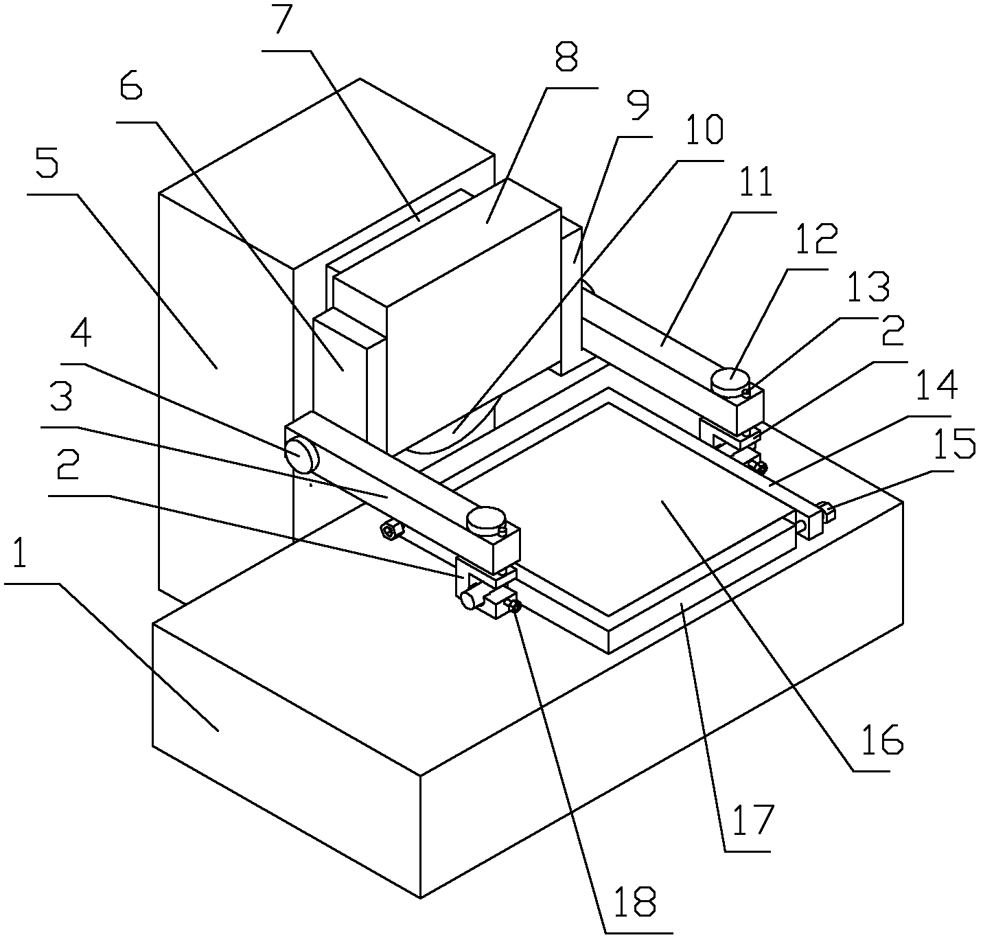
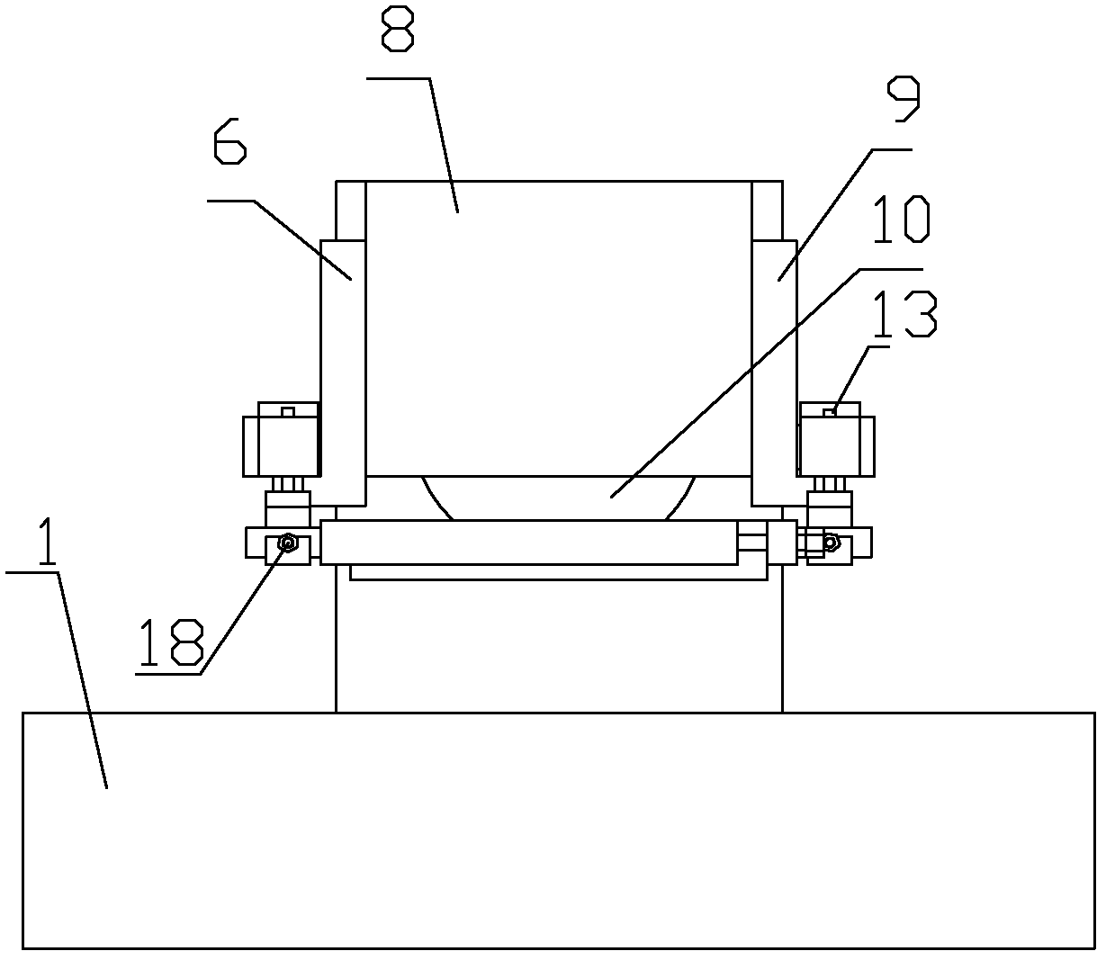
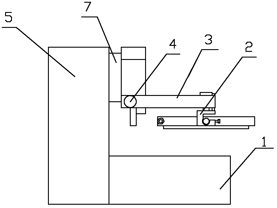
[0027] see Figure 1~6 , the embodiment of the present invention is provided with grinding machine table 1, rotating shaft block 2, left lifting arm 3, fixed arm end cover 4, grinding machine column 5, left fixed arm 6, grinding machine headstock 7, grinding wheel cover 8, right fixed arm 9, Grinding wheel 10, right lifting arm 11, rotating shaft block end cover 12, positioning pin 13, right clamping arm 14, locking screw 15, workpiece 16, left clamping arm 17, positioning screw 18.

[0028]The left fixed arm 6 and the right fixed arm 9 of the auxiliary loading and unloading mechanism are installed on the grinding wheel cover 8 both sides on the surface grinder spindle box 7 . The left lifting arm 3 and the right lifting arm 11 are all provided with round holes, which are correspondingly installed on the convex round table shafts of the left fixed ar...


PUM


Abstract

The invention provides an auxiliary up-and-down feeding mechanism of a surface-grinding machine, relating to a grinding machine. The invention aims to provide an auxiliary up-and-down feeding mechanism of the surface-grinding machine, which can ensure the flexibility and reliability of the workpiece up-and-down feeding operations in a high-precision grinding process and is used for processing optical elements of the high-precision large-diameter surface-grinding machine. The mechanism is provided with a left fixed arm, a right fixed arm, fixed arm end covers, a left lifting arm, a right lifting arm, a left clamping arm, a right clamping arm, revolving shaft pieces, a revolving shaft piece end cover and a lock screw, wherein the round holes are arranged on the left and right lifting arms and are positioned on convex boss shafts of the left and right lifting arms, rolling bearings are arranged between the round holes and the convex boss shafts, and the left and right lifting arms are fixed on the left and right fixed arm through the fixed arm end covers; the two revolving shaft pieces are respectively arranged on the front ends of the left and right lifting arms, the convex boss shafts on the revolving shaft pieces are equipped with the rolling bearings and are arranged in the round holes on the front ends of the left and right lifting arms, and are fixed on the left and right lifting arms through the revolving shaft pieces; the convex boss shafts are arranged on the left and right clamping arms and the inner sides of the left and right clamping arms are pasted with rubber strips.

Description

technical field [0001] The invention relates to a grinding machine, in particular to an auxiliary loading and unloading mechanism for optical elements of a high-precision large-diameter surface grinder. Background technique [0002] The machine tool loading and unloading mechanism or manipulator is an automatic device with the function of grabbing and moving workpieces used in the automated production process. This type of manipulator has been used more and more widely. In the machinery industry, it can be used for parts assembly, handling, loading and unloading of processed workpieces, especially in automatic CNC machine tools and combined machine tools. Automated and unmanned cutting. The existing automatic or auxiliary loading and unloading manipulators for machine tools are all independent structures, and have installation methods such as ground base type or ceiling suspension type, and are usually used in the field of mechanical rough machining. [0003] For grinding ...

Claims


Application Information

Patent Timeline
Patent Type & Authority Applications(China)
IPC IPC(8): B24B41/06B24B41/00
Inventor 王振忠郭隐彪潘日
Owner XIAMEN UNIV
Learn More