
Etching machine

An etching machine and etching technology, applied in the field of etching machines, can solve the problems of reduced transmission effect, reduced work efficiency, unreasonable design, etc., to reduce the increase in failure rate, prevent the pool effect, and improve the effect of plate making.

Inactive Publication Date: 2012-06-13
特新电路材料(东莞)有限公司
View PDF5 Cites 24 Cited by
  • Summary
  • Abstract
  • Description
  • Claims
  • Application Information

AI Technical Summary

Problems solved by technology

[0005] 1. The development, etching and film removal processes cannot be concentrated on the same equipment at the same time, and the production requirements can not be completed at one time. At the same time, the degree of automation is low, and the production equipment lacks a control system, resulting in many adjustments on the equipment requiring manual operation. Reduced work efficiency
[0006] 2. During the transmission of printed circuit boards, problems such as slipping and offset are prone to occur, resulting in reduced transmission effects and affecting the effects of developing, etching and film removal
[0007] 3. During the etching process, due to the unreasonable structural design of the equipment, the etching liquid flows out from the edge area of ​​the circuit board, while the central area of ​​the circuit board accumulates to form a pool and produce a pool effect
[0008] 4. With the continuous expansion of the production scale of printed circuit boards, a lot of waste will naturally be generated. Due to the poor filtration and recovery effect and unreasonable design of the existing printed circuit board production equipment, the pollution of the waste to the indoor and outdoor environments has already Seriously affect the working and living environment, and there are many recyclable raw materials in the waste, resulting in waste and increased production costs

Method used


Image

  • Etching machine
  • Etching machine
  • Etching machine

Examples


Embodiment Construction

[0045] The present invention will be described in detail below in conjunction with the accompanying drawings.

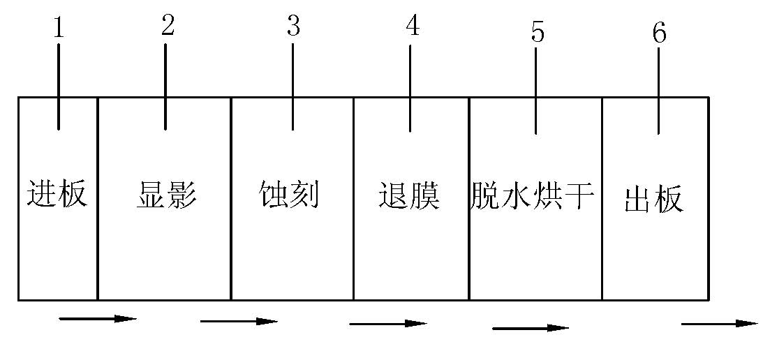
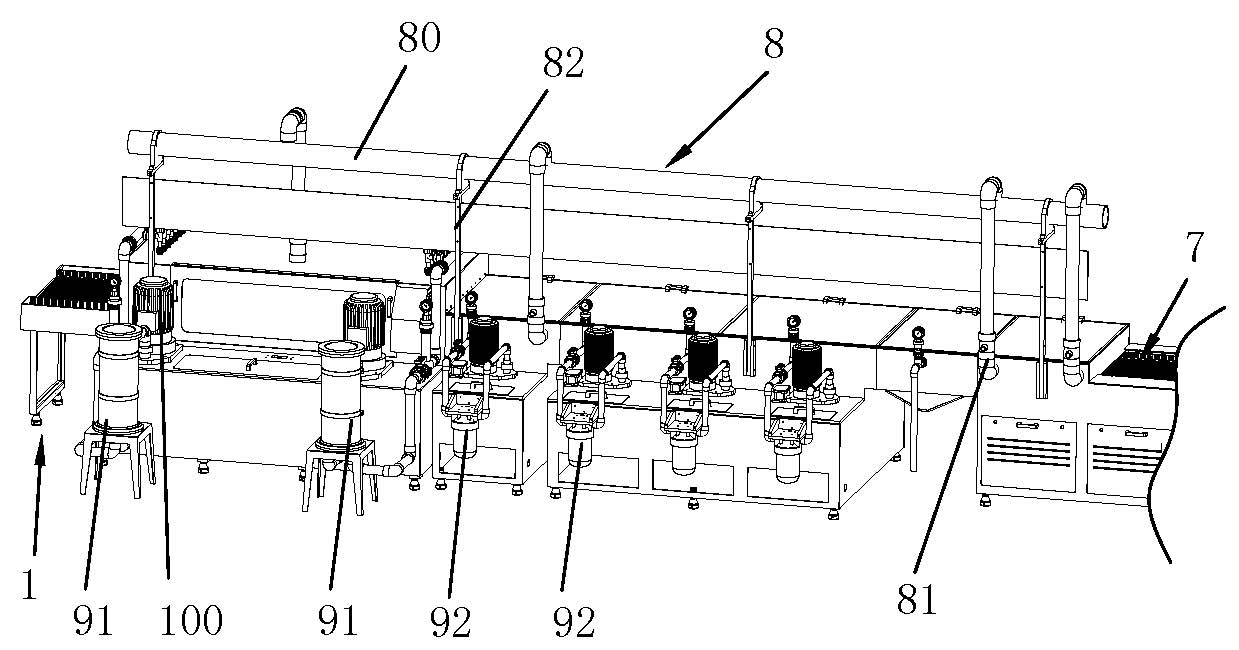
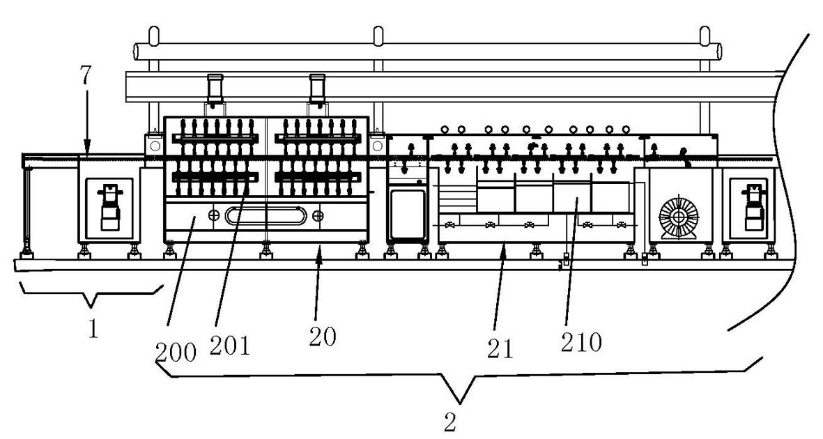
[0046] Such as Figure 1 to Figure 18 As shown, an etching machine includes a control system and a plate feeding mechanism 1, a developing mechanism 2, an etching mechanism 3, a film removing mechanism 4, a dehydration drying mechanism 5 and a plate discharging mechanism 6, which are electrically connected to the control system and arranged in sequence. , the plate feeding mechanism 1, the developing mechanism 2, the etching mechanism 3, the film removing mechanism 4, the dehydration and drying mechanism 5 and the plate discharging mechanism 6 are connected by an independently provided transmission device 7, and the developing mechanism 2, the etching mechanism 3 and the film removing mechanism 4 The segmented exhaust device 8, filter device and pump device are respectively connected, and an operation panel of the control system is arranged outside the body of the et...


PUM


Abstract

The invention discloses an etching machine, comprising a control system and a board feeding mechanism, a develop mechanism, an etching mechanism, a film stripping mechanism, a dehydration drying mechanism and a boarding ejecting mechanism that are connected with the control system and arranged successively. The board feeding mechanism, the develop mechanism, the etching mechanism, the stripping mechanism, the dehydration drying mechanism and the boarding ejecting mechanism are connected through individually arranged gearings; the develop mechanism, the etching mechanism and the stripping mechanism are respectively connected with sectional exhaust apparatuses, filtering apparatuses and pumping units. The invention can organically combine operations of development, etching and film stripping and complete a whole manufacture process in one piece of equipment, has high degree of automation, reasonable design, good plating and filtering recovery effects and brings huge benefits to relative industries.

Description

technical field [0001] The invention relates to the technical field of printed circuit board production equipment, in particular to an etching machine. Background technique [0002] With the rapid development of electronic technology, the integration of printed circuit boards is getting higher and higher, and the conductive lines of printed circuit boards are made more and more finely. This requires strict control, reduced tolerances, and better uniformity when producing printed circuit boards. . [0003] The existing wet-type printed circuit board production equipment has low cost and simple operation, and is widely used in the production of printed circuit boards. The basic process of printed circuit board production generally includes the development process, etching process and film removal process. The development process refers to the use of developer solution to dissolve the part of the film that has not been irradiated by ultraviolet rays, and the part that has been...

Claims


Application Information

Patent Timeline
Patent Type & Authority Applications(China)
IPC IPC(8): C23F1/08
Inventor 欧阳建英梁启光
Owner 特新电路材料(东莞)有限公司
Learn More