
Method for adjusting tensioning wheel indicator of timing system of engine

A technology of timing system and adjustment method, which is applied in the direction of engine components, machines/engines, transmissions, etc., and can solve problems such as loosening of the tension wheel pointer, unaccounted for, and tooth jumping

Active Publication Date: 2012-06-13
长城汽车股份有限公司平湖分公司
View PDF4 Cites 2 Cited by
  • Summary
  • Abstract
  • Description
  • Claims
  • Application Information

AI Technical Summary

Problems solved by technology

This adjustment method does not take into account the actual assembly of the engine, thus ignoring the gap between the belt and the pulley and the tolerance of each pulley, resulting in the elimination of the meshing gap between the belt and the pulley during the running-in stage of the engine due to force, which will cause the tension wheel pointer Back loose, the tension becomes smaller, and there is a hidden danger of tooth jumping during the cold start and operation of the engine

Method used


Image

  • Method for adjusting tensioning wheel indicator of timing system of engine
  • Method for adjusting tensioning wheel indicator of timing system of engine
  • Method for adjusting tensioning wheel indicator of timing system of engine

Examples


Embodiment Construction

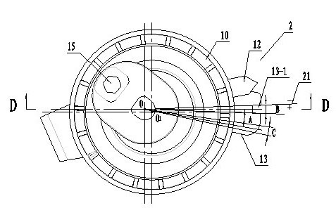
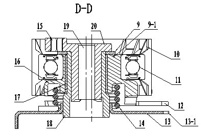
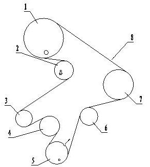
[0017] see image 3 , the engine timing system includes camshaft timing pulley 1, tension pulley 2, oil pump timing pulley 3, idler pulley 4, crankshaft timing pulley 5, water pump pulley 6 and Fuel pump timing pulley 7. The camshaft timing pulley, the fuel pump timing pulley, the crankshaft timing pulley, and the oil pump timing pulley mesh with the timing belt respectively. The function of the timing system is to ensure that the crankshaft and camshaft rotate synchronously at all times. The synchronous rotation requirement is: the crankshaft rotates twice, the camshaft rotates once, that is, the piston walks a full stroke, and the intake and exhaust valves are opened and closed once. When installing, turn the crankshaft timing pulley to the first and fourth cylinder pistons at the top dead center, that is, the groove mark on the crankshaft pulley 5 is aligned with an arrow mark on the engine casing. Both the crankshaft timing pulley and the camshaft timing pulley are provi...


PUM


Abstract

The invention relates to a method for adjusting a tensioning wheel indicator of a timing system of an engine, which is used for solving the problems that the tensioning wheel indicator is easily unjammed and a tensioning force becomes small by adopting a traditional method for adjusting the tensioning wheel indicator of the timing system of the engine. According to the method, the best initial position for adjusting the tensioning wheel indicator is found out through a sampling test, and then, the position of the tensioning wheel indicator of the timing system is adjusted according to the actual indicator adjustment range found out by the sampling test, thereby, a mesh clearance between an engine wheel set and a belt is offset, so that the indicator is unjammed to a nominal range after the engine normally wears in and is cooled. By adopting the method, the adjustment position of the tensioning wheel indicator of the timing system can be accurately determined, thereby, the tensioning wheel indicator of the timing system is prevented from being unjammed, and the engine is prevented from generating a slippage phenomenon.

Description

technical field [0001] The invention relates to a method for adjusting a tension wheel, in particular to a method for adjusting a pointer of a tension wheel in a timing system of an automobile engine, and belongs to the field of automobile manufacturing. Background technique [0002] The timing system is an important part of the engine valve train, and one of the important factors to ensure the smooth breathing of the engine. The role of timing is that when the engine is running, the stroke of the piston, the opening and closing of the valve, and the order of ignition, under the connection of "timing", must keep "synchronous" operation at all times. Through the timing mechanism of the engine, let each cylinder just do: when the piston goes up just to the top dead center, the valve just closes, and the spark plug just ignites. see image 3 , The timing system includes timing belt, camshaft timing pulley, oil pump timing pulley, crankshaft timing pulley, fuel pump pulley,...

Claims


Application Information

Patent Timeline
IPC IPC(8): F16H7/08F01L1/348
Inventor 位策牛少松王翔刘志强
Owner 长城汽车股份有限公司平湖分公司
Learn More