Electric dynamometer

A technology of electric dynamometer and variable frequency motor, applied in the field of construction machinery, can solve the problems of high cost, inability to realize forward and reverse driving, and low energy utilization rate, etc.

Inactive Publication Date: 2014-07-23
BEIJING SANY HEAVY MASCH CO LTD
View PDF4 Cites 0 Cited by
  • Summary
  • Abstract
  • Description
  • Claims
  • Application Information

AI Technical Summary

Problems solved by technology

[0009] The technical problem to be solved by the present invention is to provide an electric dynamometer, which is used to solve the problems of high cost, inability to realize positive and negative drag, and low energy utilization rate in the prior art

Method used


Image

  • Electric dynamometer
  • Electric dynamometer
  • Electric dynamometer

Examples


Embodiment Construction

[0034] In order to make the above objects, features and advantages of the present invention more comprehensible, specific implementations of the present invention will be described in detail below in conjunction with the accompanying drawings.

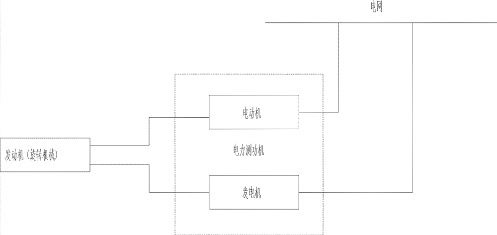
[0035] The invention provides an electric dynamometer, which is used to solve the problems in the prior art such as high cost, inability to realize positive and negative dragging, and low energy utilization rate.

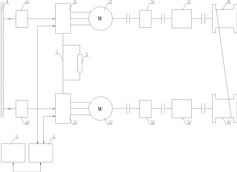
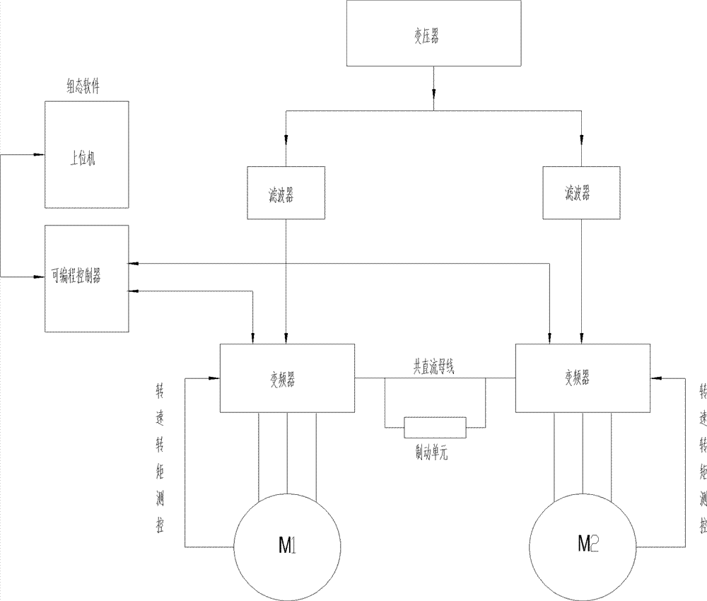
[0036] The electric dynamometer described in the embodiment of the present invention includes a mechanical transmission system and a frequency conversion control system.

[0037] The mechanical transmission system includes two groups of transmission subsystems, namely, the first transmission subsystem and the second transmission subsystem, which are symmetrically arranged and connected to rotate in the same direction, and positively and negatively drag each other.

[0038] The first transmission subsystem includes a first va...


PUM


Abstract

An electric dynamometer comprises a mechanical transmission system and a frequency conversion control system. The mechanical transmission system comprises two sets of transmission subsystems. The two sets of transmission subsystems are symmetrically arranged and connected in a way of rotating in the same direction, and drive each other forwards and backwards. Each set of transmission subsystem comprises a variable frequency motor (21, 22) and a speed reducer or an accelerator (31, 32). The speed reducers or accelerators (31, 32) of the two set of transmission subsystems are connected with a rotating part under test (41) and a rotating part for control test (42) respectively. The rotating part under test (41) and the rotating part for control test (42) are flexibly connected, and synchronously rotate. The frequency conversion control system comprises two frequency converters (11, 12). The two frequency converters (11, 12) are respectively connected with the variable frequency motor (21, 22) of the two sets of transmission subsystems. The two frequency converters (11, 12) are connected through a direct current bus (1). The frequency conversion control system performs closed loop control on the variable frequency motors (21, 22) through the frequency converters (11, 12). The electric dynamometer is used for solving the problems in the prior art such as a high cost, incapability of implementing forward and backward driving, and a low energy utilization rate.

Description

technical field [0001] The invention relates to the technical field of engineering machinery, in particular to an electric dynamometer. Background technique [0002] At present, dynamometers are usually used as loading equipment for controlling the torque and speed of rotating machinery in the world. The dynamometer industry in my country has a low level of manufacturing technology, unstable performance, and is in the stage of product imitation. Moreover, both power and loading require energy consumption, especially for tests with large loads and long test times, the cost of energy consumption has become a heavy burden for enterprises. [0003] Dynamometers are generally divided into hydraulic dynamometers, eddy current dynamometers, and electric dynamometers. [0004] The hydraulic dynamometer has the dynamic characteristics of low speed and low torque, high speed and high torque. It is not suitable for test loading of rotating machinery with low speed and high torque, and...

Claims


Application Information

Patent Timeline
Patent Type & Authority Patents(China)
IPC IPC(8): G01L3/24
CPCG01L3/24
Inventor 孙卫波
Owner BEIJING SANY HEAVY MASCH CO LTD
Why Eureka
Try Eureka