
Device and method for detecting movement state of load-bearing steel wire rope

A detection device, a technology of motion state, applied in the direction of measuring device, indication/recording action, speed/acceleration/impact measurement, etc., can solve the problems of inability to accurately measure the longitudinal motion state of the wire rope, evaluation, and no wire rope detection device and method , to achieve the effect of overcoming the problem that the twisting state cannot be measured, accurate measurement, and compact structure

Active Publication Date: 2012-06-13
CHINA UNIV OF MINING & TECH
View PDF4 Cites 5 Cited by
  • Summary
  • Abstract
  • Description
  • Claims
  • Application Information

AI Technical Summary

Problems solved by technology

The performance test under static load is mainly carried out by tensile testing machine and measured by extensometer; while the motion state measurement of steel wire rope under dynamic load is generally measured by connecting the shaft encoder to the top guide wheel. Displacement, but can not measure the vibration state of the wire rope movement process; the existing motion state detection of the acceleration, velocity and displacement of the end of the wire rope is only limited to the use of acceleration sensors to determine, and can only approximate the longitudinal and lateral motion state
It can be seen that the current detection device for the motion state of the steel wire rope cannot accurately measure the longitudinal motion state of the wire rope, and there is no detection device and method for the torsion state of the wire rope, so it is impossible to grasp the motion changes of the wire rope during the lifting and lowering process, let alone evaluate Some important working conditions, such as: the operating state of the hoisting rope of the ultra-deep construction shaft hoisting bucket, the motion state of the crane during the process of lifting heavy objects, and the motion state of the helicopter suspension rope during the process of lifting heavy objects

Method used


Image

  • Device and method for detecting movement state of load-bearing steel wire rope
  • Device and method for detecting movement state of load-bearing steel wire rope
  • Device and method for detecting movement state of load-bearing steel wire rope

Examples


Embodiment Construction

[0019] Embodiments of the present invention will be further described below in conjunction with the accompanying drawings:

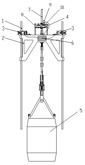
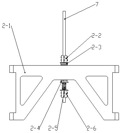
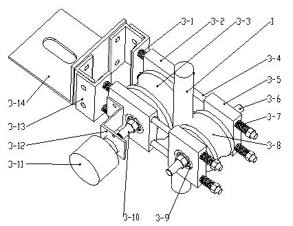
[0020] The steel wire rope motion state detection device of the present invention mainly consists of a guide rope 1 for longitudinal motion state detection, a signal collector 6, a carriage device 2 that moves along the guide rope 1, and is fixed on the carriage device 2 and moves along the guide rope 1. Sliding longitudinal motion detection device 3, twist detection device 4 fixed on the carriage 2 and clamped on the detection wire rope 7, and a counterweight device 5 fixed at the end of the detection wire rope 7 constitute. The carriage device 2 includes a carriage 2-1, two upper and lower steel wire rope clamping blocks 2-2, 2-6 arranged on the carriage 2-1, and upper and lower clamping blocks 2-2, 2-6. There are upper and lower thrust bearings 2-3, 2-4 between 6 and the carriage 2-1, and a preload spring 2-5 between the lower clamping block 2-6 and t...


PUM


Abstract

Disclosed are a device and a method for detecting the movement state of a load-bearing steel wire rope. The device comprises a guide rope, a signal acquisition device, a sliding frame, a longitudinal movement detecting device, a twist detecting device and a counter weight, wherein the sliding frame moves along with the guide rope, the longitudinal movement detecting device is fixed onto the sliding frame and slides along with the guide rope, the twist detecting device is fixed onto the sliding frame and clamped on the steel wire rope to be detected, and the counter weight is fixed to the tail end of the steel wire rope to be detected. When the steel wire rope is detected during movement, the sliding frame is fixed onto the steel wire rope to be detected through clamp blocks to move up and down, a guide wheel in the longitudinal movement detecting device for the steel wire rope rolls along with the guide rope at a high speed, the rolling state of the guide wheel is measured by a shaft encoder, twist of the steel wire rope drives a friction wheel in the twist detecting device to rotate, the movement state of the friction wheel is measured by the shaft encoder connected with the friction wheel, measuring data are acquired by the signal acquisition device, and signals are outputted to an industrial personal computer, so that the movement state of the steel wire rope is detected.

Description

technical field [0001] The invention relates to a device and method for detecting the motion state of a load-bearing steel wire rope, and is especially suitable for detecting the motion state of different load-bearing ropes and the motion state of a construction shaft bucket. Background technique [0002] At present, the detection of the bearing state of the steel wire rope is mainly the performance detection under the static load and the motion state detection under the dynamic load. The performance test under static load is mainly carried out by tensile testing machine and measured by extensometer; while the motion state measurement of steel wire rope under dynamic load is generally measured by connecting the shaft encoder to the top guide wheel. Displacement, but the vibration state of the wire rope movement process cannot be measured; the existing motion state detection of the acceleration, velocity and displacement of the end of the wire rope is limited to the determina...

Claims


Application Information

Patent Timeline
Patent Type & Authority Applications(China)
IPC IPC(8): G01P13/00
Inventor 曹国华朱真才王进杰彭维红周公博李伟彭玉兴宋静吴荣华曹永光王淼王东亮
Owner CHINA UNIV OF MINING & TECH
Learn More