System and method for debugging FPGA (field programmable gate array)

A debugging system and signal acquisition technology, which is applied in the field of FPGA debugging system, can solve problems such as information flooding, real-time data storage problems, invalidity, etc., and achieve the effect of increasing data volume and quickly locating problems

Active Publication Date: 2012-06-13
DAWNING INFORMATION IND BEIJING +1
View PDF4 Cites 15 Cited by
  • Summary
  • Abstract
  • Description
  • Claims
  • Application Information

AI Technical Summary

Problems solved by technology

[0004] 1) This method is invalid for systems without network ports
[0005] 2) Only real-time observation of FPGA logic internal signals can be performed, and key trigger points cannot be set to record information. The problem brought about by this is that a small amount of information required for debugging is submerged in a large amount of real-time data, and the storage of these real-time data is a problem

Method used


Image

  • System and method for debugging FPGA (field programmable gate array)
  • System and method for debugging FPGA (field programmable gate array)

Examples


Embodiment Construction

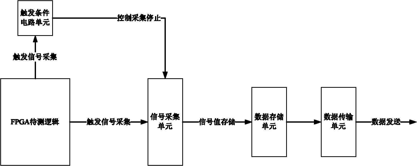
[0025] The present invention proposes a kind of FPGA debugging method, specifically as follows:

[0026] 1) Add a trigger condition circuit unit for debugging and a signal acquisition unit for collecting key signals in the FPGA logic.

[0027] 2) Allocate signal acquisition resources, that is, data storage units, according to the usage of FPGA storage resources (on-chip RAM, off-chip DDR SDRAM or SRAM, etc.), and then set the signal acquisition depth n according to the number of acquisition signals, that is, acquisition and storage number of cycles.

[0028] 3) The collected data is stored in the data storage unit in a first-in-first-out manner. When the storage resources of the data storage unit are used up, the data collected later squeezes out the data collected earlier.

[0029] 4) When n / 2 cycles after the trigger condition is satisfied, the trigger condition circuit unit controls the signal acquisition unit to stop acquisition.

[0030] 5) The data transmission unit tr...


PUM


Abstract

The invention provides a system and a method for debugging an FPGA (field programmable gate array). The system comprises an FPGA logic module to be tested, a signal acquisition unit module, a trigger condition circuit unit module and a data transmission unit module, wherein the signal acquisition unit module acquires trigger signals transmitted from the FPGA logic module to be tested, and the trigger condition circuit unit module controls stopping of signal acquisition of the signal acquisition unit. The method adds a trigger condition circuit unit for debugging and a signal acquisition unit for acquiring key signals. The system and the method for debugging the FPGA have the advantages that external cables in debugging are omitted, the system is convenient to use, external high-capacity storage resources of the FPGA can be used, analyzable data volume after condition trigger is increased, and rapider positioning is benefited.

Description

technical field [0001] The invention belongs to the technical field of digital integrated circuits, and in particular relates to an FPGA debugging system and method. Background technique [0002] In the prior art, the FPGA debugging method is cumbersome and requires a lot of manpower and time. In the prior art, there are two commonly used FPGA debugging methods, one is to connect the signals that need to be checked inside the FPGA to the FPGA pins, and then use an expensive logic analyzer to connect these pins to analyze the signals; the other is to Use an external cable to connect to the FPGA through the JTAG interface, set the trigger conditions through the software logic analyzer provided by Xilinx or Altera, and analyze the problem by analyzing the captured waveform after the condition is triggered. The first solution requires an expensive logic analyzer, and the second solution needs to insert a logic analysis unit provided by the FPGA manufacturer into the FPGA logic....

Claims


Application Information

Patent Timeline
Patent Type & Authority Applications(China)
IPC IPC(8): G01R31/3185
Inventor 窦晓光张英文李静纪奎邵宗有
Owner DAWNING INFORMATION IND BEIJING
Why Eureka
Try Eureka