
Pressure relief apparatus of high voltage switch cabinet

A high-voltage switchgear and pressure relief device technology, applied in the direction of switchgear, switchgear settings, electrical components, etc., can solve the problems of unfavorable safe operation of switchgear, potential safety hazards of operators, and easy injury or damage to equipment. To achieve the effect of improving practical safety, ensuring safety in use, and ensuring safety

Active Publication Date: 2015-05-20
ANHUI ZHONGDIAN XINGFA & XINLONG TECH CO LTD
View PDF4 Cites 2 Cited by
  • Summary
  • Abstract
  • Description
  • Claims
  • Application Information

AI Technical Summary

Problems solved by technology

Although this kind of pressure relief device can reduce the pressure in the busbar room in case of failure and ensure the safety of the equipment, if there are people in the power distribution room at this time, it will easily become a safety hazard for the operator; in general, this kind of high-voltage switchgear has the following defects :
[0003] First, when the pressure in the busbar room is increased due to a fault in the busbar room, when the pressure relief cover is rushed out, the pressure relief cover will fly randomly in the power distribution room, which is easy to injure or damage other equipment. It is easy to pose a safety hazard to the operator;
[0004] Second, the pressure relief cover completely seals the busbar room as a whole, which is not conducive to the heat dissipation of the switchgear and is not conducive to the safe operation of the switchgear

Method used


Image

  • Pressure relief apparatus of high voltage switch cabinet
  • Pressure relief apparatus of high voltage switch cabinet
  • Pressure relief apparatus of high voltage switch cabinet

Examples


Embodiment Construction

[0026] The specific implementation manner of the present invention will be described in further detail below by describing the best embodiment with reference to the accompanying drawings.

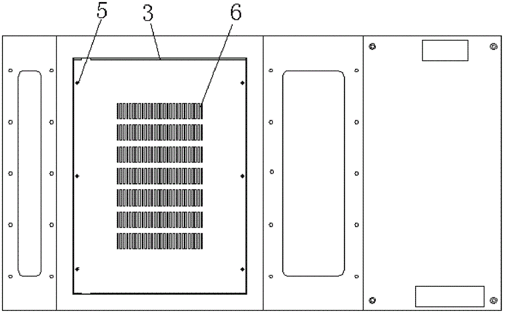
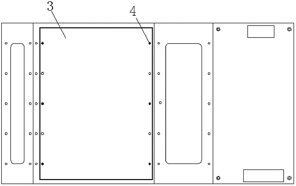
[0027] Such as figure 1 and figure 2 As shown, the high-voltage switchgear pressure relief device includes a cabinet body 1, and a pressure relief cover 3 is provided above the busbar chamber 2 of the cabinet body 1. The pressure relief cover 3 and the busbar chamber 2 are connected by metal screws 5. The cover 3 is provided with a pressure relief hole 6 .

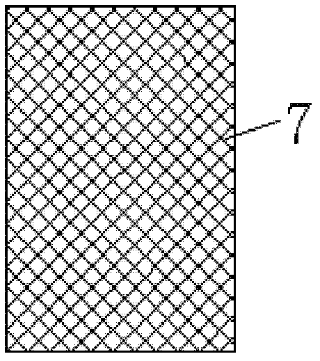
[0028] A wire mesh 7 is provided below the position where the pressure relief hole 6 is provided on the pressure relief cover 3, and the wire mesh 7 is welded on the pressure relief cover 6; the wire mesh 7 can strengthen the pressure relief at the place where the pressure relief hole 6 is provided The strength of the cover 3 prevents the position of the pressure relief cover 3 at the pressure relief hole 6 from being broken when the...


PUM


Abstract

The invention discloses a pressure relief apparatus of a high voltage switch cabinet. The apparatus includes a cabinet body; a pressure relief cover is arranged above a busbar chamber of the cabinet body; the pressure relief cover and the busbar cover are connected by metal screws; and pressure relief holes are arranged on the pressure relief cover. According to the pressure relief apparatus provided by the invention, it can be ensured that high voltage switch cabinet equipment can carry out operation safely; and safety of working personnel can also be ensured; meanwhile, heat radiation of the high voltage switch cabinet can be carried out conveniently.

Description

technical field [0001] The invention relates to the field of electrical switches, in particular to a pressure relief device for a high-voltage switch cabinet. Background technique [0002] In the current power system, the middle-mounted (KYN28-12) AC closed high-voltage switchgear, such as figure 2 , image 3 and Figure 4 As shown, including the cabinet body, a pressure relief cover is installed above the busbar chamber of the cabinet body, and the pressure relief cover is connected with the busbar chamber by plastic screws; the purpose is to prevent any short-circuit fault in the busbar chamber, resulting in a sharp increase in the internal pressure of the busbar chamber. , The pressure relief cover can be flushed open to achieve the purpose of pressure relief inside the cabinet and ensure the safe operation of the high-voltage switchgear. Although this kind of pressure relief device can reduce the pressure in the busbar room in case of failure and ensure the safety of ...

Claims


Application Information

Patent Timeline
IPC IPC(8): H02B13/025
Inventor 束龙胜李开明宛玉超孙国才付强周波王坤王春玲李卫华杨成长
Owner ANHUI ZHONGDIAN XINGFA & XINLONG TECH CO LTD
Learn More