Eureka AIR delivers breakthrough ideas for toughest innovation challenges, trusted by R&D personnel around the world.

Piston-chamber hydro-gravity engine

A piston chamber and engine technology, applied in the direction of reciprocating piston engines, engine components, variable displacement engines, etc., can solve problems such as insufficient production, unreasonable safety standards, unreliable economy, etc., and achieve the goal of solving environmental and energy problems Effect

Inactive Publication Date: 2012-06-13
斯特法诺斯・恩图科利亚诺斯 +1
View PDF0 Cites 7 Cited by
  • Summary
  • Abstract
  • Description
  • Claims
  • Application Information

AI Technical Summary

Problems solved by technology

[0027] It is clear that existing technologies for harnessing energy, such as fossil fuel, atomic, solar, wind and geothermal power generation, are done in ways that are economically unreliable, inadequate, unreasonable by world safety standards, and insufficient to generate sufficient energy to meet global demands in the near future. The energy needed by 6.5 billion people in the world

Method used


Image

  • Piston-chamber hydro-gravity engine
  • Piston-chamber hydro-gravity engine
  • Piston-chamber hydro-gravity engine

Examples


Embodiment Construction

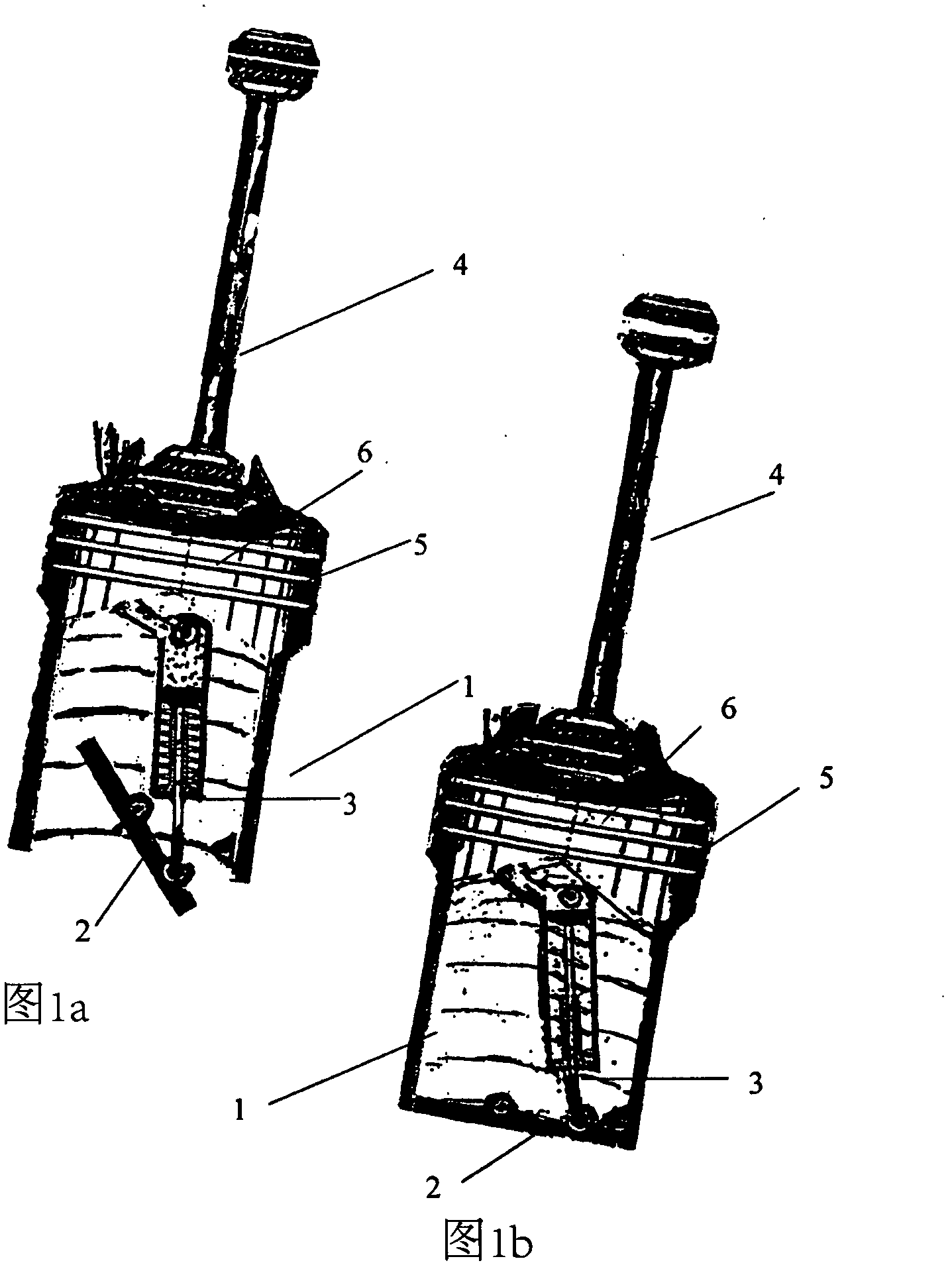
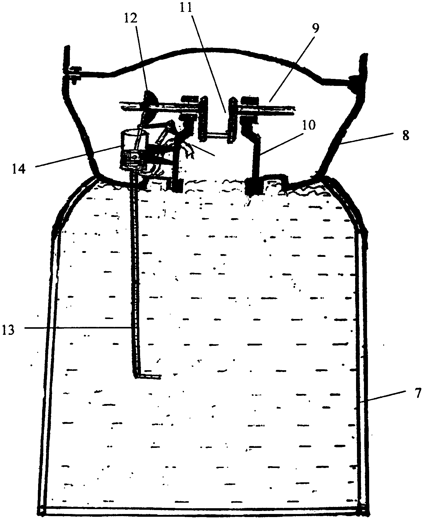
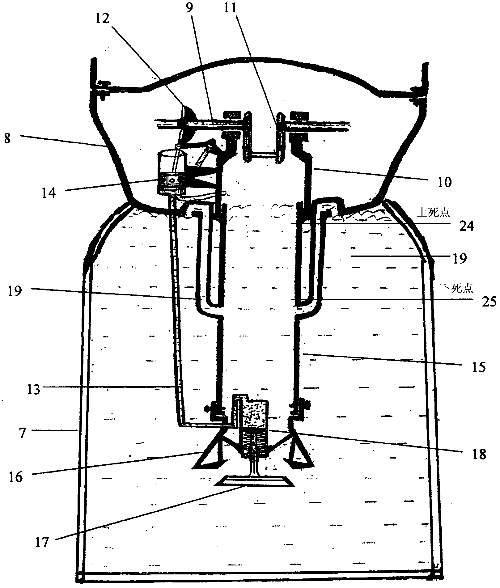
[0100] The detailed description of the present invention and the accompanying drawings describe the working mode of the technical design of the piston chamber liquid gravity engine determined according to the method currently invented, and are only used for explaining examples rather than limiting the present invention. In particular, the description and the accompanying drawings Diagrams are used to show the concept of the method and the mode of design of this piston chamber liquid gravity engine technology, how it utilizes the modes of gravitational liquid static and liquid gravity forces and how the liquid gravity forces are converted to a mechanically reproducible engine that can be applied in various ways Active energy, rather than limiting the method and the piston chamber liquid gravity engine system designed using the method technology.

[0101] image 3 A liquid container (7) is shown filled with a hermetically isolated liquid substance.

[0102] The outer sealing su...


PUM


Abstract

A piston-chamber hydro-gravity engine capable of converting the stagnant volume of the liquid matter of sea, lake, pond or artificially made hydro container, to a moving volume of liquid matter that flows back upon itself and in meanwhile exploits this motion as a working agent to produce mechanical kinetic power, capable of being used for mechanical production of kinetic work for hydro-electricity generation, or to be used multi-purposely for other energy needs that demand mechanical kinetic force sufficient to solve energy production problems worldwide forever beneficial to the economy and, friendly to the environment, consisting of particular accessories of mechanisms embodied in a single system of mutual successive co-operation by exploiting gravity, that is the hydro-container (7),; capable of creating the means of exploiting the gravity-hydro-static tension of squashing compression exist within the volume of liquid matter of the sea, lake, pond or artificially made containers, the cylinder-chamber (15) and piston-chamber (1) these convert the stagnant gravity- hydro-static tension of force into a fluctuating homo-acting and counter-acting to gravity hydro-gravity-moving-force of action, that compels the piston-chamber (1) to reciprocate, the hermetically sealed vessel crank-cam-shaft chamber (8) operating as a participator in creating the means of the system piston-chamber hydro-gravity engine's function and meanwhile participating in the embodiment system that converts the reciprocating motion of piston-chamber (1), to a rotating motion capable of being used multi-purposely,; where for the piston-chamber hydro-gravity engine to function it is necessary for the hydro-gravity force of action of conduits (19) to be less than the hydro-gravity force of action of piston-chamber (1), the area where conduits (19) adjusted hermetically fixed at the trunk of the cylinder-chamber (15) to be under the B.D.C. of piston-chamber (1).

Description

technical field [0001] The invention relates to a method for designing a technical system producing small and large volumes of mechanical power work for multipurpose use, characterized by a piston chamber liquid gravity engine whose piston chamber (not that of existing piston engines Piston) utilizes gravity, by converting gravity into liquid gravity, and using liquid gravity as its operating medium, specifically the liquid on which gravity exerts force, utilizing the natural combination of liquid to combine liquid gravity and confining the liquid in it The static resistance of the solid walls of a natural basin or man-made container that converts this combination of liquid gravitational forces into a stagnant gravitational liquid static resultant force of outward and inward pressurized compressive liquid stresses that includes three opposing actions Force, described as the static resistance of gravity, liquid matter, and solid matter making up the walls of natural watersheds ...

Claims


Application Information

Patent Timeline
IPC IPC(8): F03B17/04F03G7/10
CPCF03G7/10F03C1/002Y02E10/20F03B17/04
Inventor 斯特法诺斯·恩图科利亚诺斯
Owner 斯特法诺斯・恩图科利亚诺斯
Why Eureka
Eureka Blog
Learn More