
Method and arrangement in a mobile communications system

A device and signal technology, applied in the field of mobile communication systems, can solve problems such as reducing efficiency, and achieve the effect of reducing the impact of shunt loss and high efficiency

Inactive Publication Date: 2012-06-13
TELEFON AB LM ERICSSON (PUBL)
View PDF4 Cites 1 Cited by
  • Summary
  • Abstract
  • Description
  • Claims
  • Application Information

AI Technical Summary

Problems solved by technology

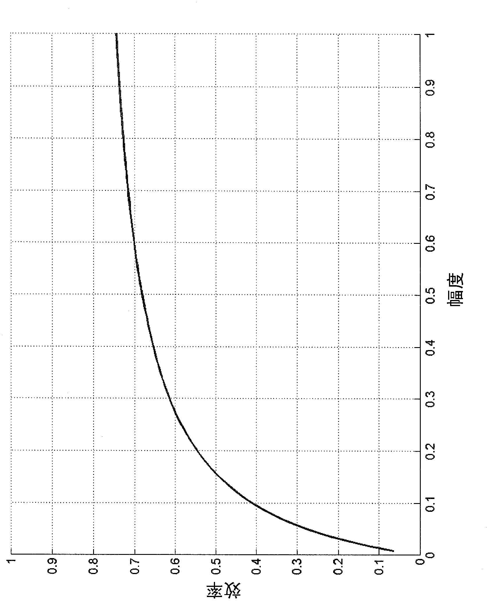
Both loss types degrade efficiency equally at all output power levels

Method used


Image

  • Method and arrangement in a mobile communications system
  • Method and arrangement in a mobile communications system
  • Method and arrangement in a mobile communications system

Examples


Embodiment Construction

[0023] The present invention will now be described more fully hereinafter with reference to the accompanying drawings, in which preferred embodiments of the invention are shown. However, the invention may be embodied in many different forms and should not be construed as limited to the embodiments set forth herein; rather, these embodiments are provided so that this disclosure will be thorough and complete, and will convey knowledge to those skilled in the art. personnel to fully convey the scope of the invention. In the drawings, like reference symbols refer to like elements.

[0024] Furthermore, those skilled in the art will appreciate that the functions and means described below can be implemented using software functions in conjunction with a programmed microprocessor or general purpose computer, and / or using an Application Specific Integrated Circuit (ASIC). It should also be understood that while the present invention has been primarily described in terms of methods an...


PUM


Abstract

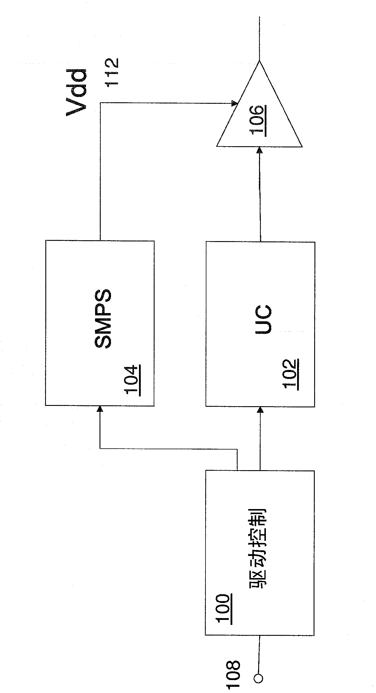
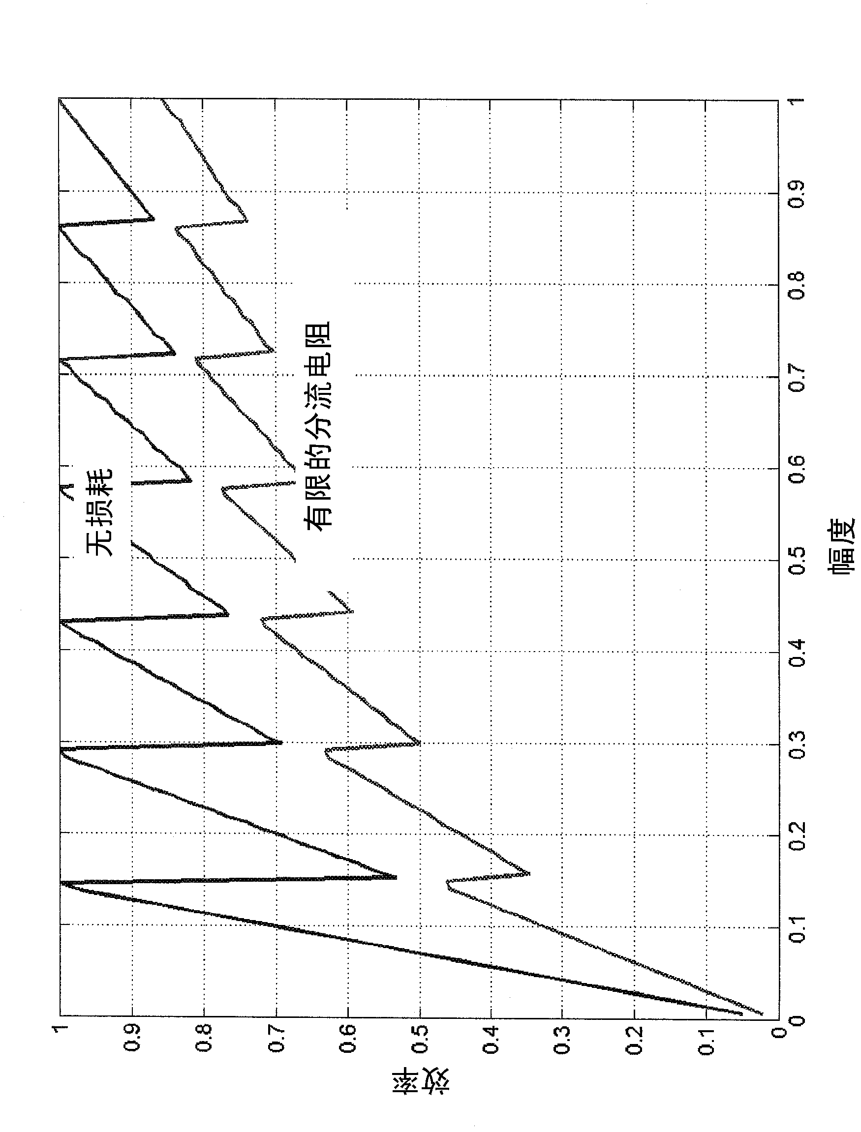
The invention is based on the fact that the current output from a DDB controlled amplifier in backoff, i.e. for low amplitudes, is reduced more or less linearly with the amplitude of the signal to be amplified. Therefore, it is enough to use smaller amplifiers which are able to output the necessary RF current. Hence, according to the present invention, the total DDB amplifier is divided into smaller parts that are coupled to the output only when needed.

Description

technical field [0001] The present invention relates to methods and devices in mobile communication systems, and in particular to DDB amplifiers with increased efficiency. Background technique [0002] Transmitters in base stations and mobile phone terminals, as well as those used in broadcast and other wireless systems, require power amplifiers (PAs) to amplify radio frequency (RF) signals fed to antennas. Such PAs often need to be very efficient in order to increase battery time, reduce energy costs, and minimize cooling requirements. [0003] Traditional Class B and Class AB PAs usually operate at constant load and constant supply voltage. "Optimal load" (Ropt) is the load that gives the highest output power under the allowable operating conditions. Class B or Class AB operation means that the transistor current pulse has approximately a quarter wavelength rectified sinusoidal waveform. The current pulses have approximately the same shape at all amplitudes, and both th...

Claims


Application Information

Patent Timeline
Patent Type & Authority Applications(China)
IPC IPC(8): H03F1/02H03F3/21H03F3/60
CPCH03F3/211H03F2203/21145H03F1/56H03F2200/378H03F2203/21139H03F2200/387H03F3/602H03F1/0277H03F1/0222H03F2200/391
Inventor 里卡德·赫尔贝里
Owner TELEFON AB LM ERICSSON (PUBL)
Learn More