
Vibration damping box with adjustable rigidity and damping

A vibration damping box and damping technology, which is applied in the direction of preventing mechanical damage to containers, containers, packaging, etc., can solve the problems that the installed vibration isolator cannot be replaced, the specifications of the vibration damping box are difficult to unify, and the vibration damping box transports a single product, etc., to achieve Adjustable vibration damping performance, not easy to roll over, uniform force effect

Inactive Publication Date: 2012-06-20
MILITARY TRANSPORTATION UNIV PLA
View PDF9 Cites 13 Cited by
  • Summary
  • Abstract
  • Description
  • Claims
  • Application Information

AI Technical Summary

Problems solved by technology

[0003] The current vibration damping box mainly includes a box body, and a vibration isolator is installed vertically in the box body, or pad paper, rubber, foam, etc. in the box body to achieve vibration reduction, so that the vibration damping box transports a single product, and the vibration damping performance cannot be adjusted. , the installation of the vibration isolator cannot be replaced, its life is short, and it cannot be reused, resulting in the problem that the specifications of the vibration-absorbing box are difficult to unify when a variety of products with different qualities and different vibration-damping requirements are mixed and transported
Moreover, the metal linear vibration isolator has a narrow vibration isolation frequency band, which makes it difficult to isolate vibration at lower frequencies during transportation.

Method used


Image

  • Vibration damping box with adjustable rigidity and damping
  • Vibration damping box with adjustable rigidity and damping

Examples


Embodiment Construction

[0019] The present invention will be described in detail below in conjunction with the accompanying drawings and specific embodiments.

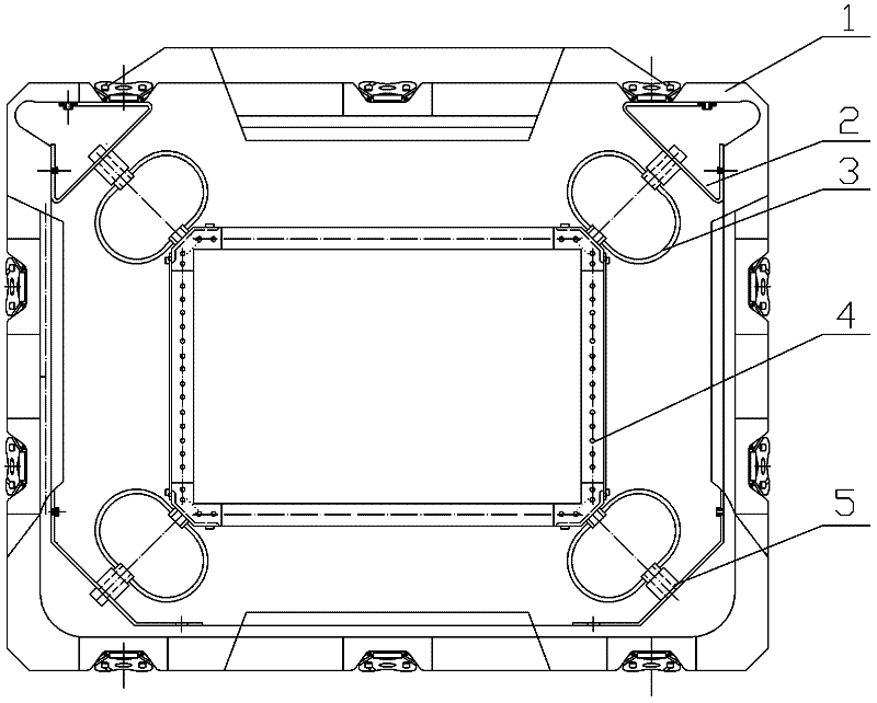
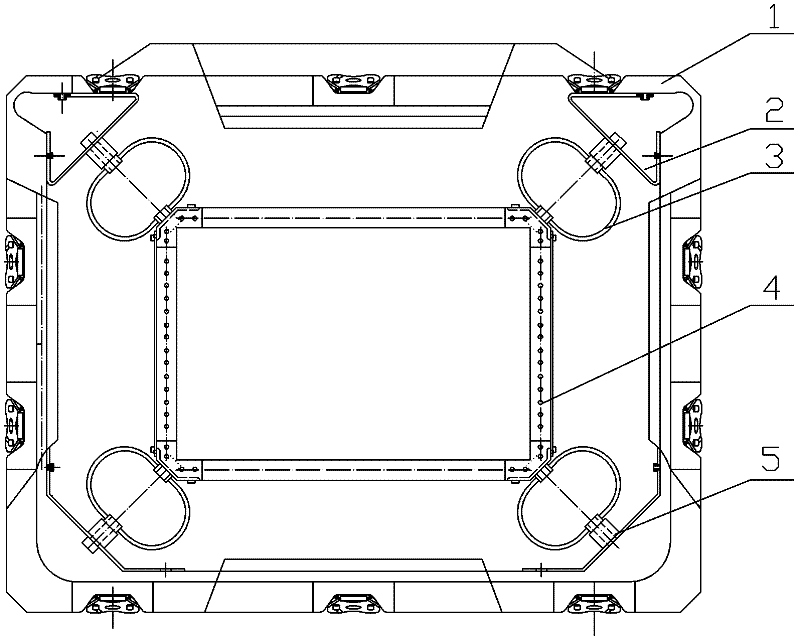
[0020] The schematic diagram of the damping box with adjustable stiffness and damping of the present invention is as follows figure 1 As shown, it includes a box body 1, a plurality of fixed supports 2 are respectively installed on the inner wall of the box body 1, a material fixing frame 4 is installed in the box body, and a plurality of material fixing holes are arranged on the material fixing frame A vibration isolator 3 is respectively installed between the material fixing frame 4 and each fixed support 2, and the acute angle between the bearing surface of each vibration isolator and the horizontal direction is 45°. Both ends of the box 1 are respectively equipped with box covers to realize sealing. Among them, the vibration isolator is preferably a vibration isolator with nonlinear and strong damping characteristics, such as a wire rope...


PUM


Abstract

The invention discloses a vibration damping box with adjustable rigidity and damping, which is suitable for transporting various boxed materials with a vibration damping requirement and has the advantages of simple structure and convenience for use. Fixing supports are respectively at corners of a box body. A material fixing frame is arranged in the box body. The material fixing frame is provided with a plurality of material fixing holes. A vibration isolator is mounted between the material fixing frame and each fixing support. An acute angle formed by the bearing surface of each vibration isolator and a horizontal direction is 45 DEG. A gasket for adjusting the mounting size of the vibration isolator is arranged between each vibration isolator and the corresponding fixing support. The vibration damping box disclosed by the invention has the beneficial effects that the vibration isolators with different vibration damping properties can be mounted between the fixing supports and the material fixing frame by changing the mounting size of each vibration isolator, so that the different vibration damping requirements of the materials in the box can be met. The vibration damping box not only can meet the vibration damping requirements of the transported materials with different quality but also can meet the vibration damping requirements of the different transportation manners by mounting different models and different types of the vibration isolators.

Description

technical field [0001] The invention relates to a damping box with adjustable stiffness and damping. Background technique [0002] With the continuous advancement of technology, the reliability requirements for precision instruments, electronic products, anti-vibration items and other equipment are getting higher and higher. Therefore, the vibration-absorbing box for loading and transporting these equipment is very important for protecting internal equipment from vibration and shock. Interference plays an important role. [0003] The current vibration damping box mainly includes a box body, and a vibration isolator is installed vertically in the box body, or pad paper, rubber, foam, etc. in the box body to achieve vibration reduction, so that the vibration damping box transports a single product, and the vibration damping performance cannot be adjusted. , The installed vibration isolator cannot be replaced, its life is short, and it cannot be reused, which makes it difficul...

Claims


Application Information

Patent Timeline
IPC IPC(8): B65D81/05B65D77/26
Inventor 陈欣蒋美华王国军李慧梅刘精强周少良李立平
Owner MILITARY TRANSPORTATION UNIV PLA
Learn More