Condensed fluid stripping method matched with CO transforming device

A technology for converting device and condensate, which is used in heating water/sewage treatment, degassing water/sewage treatment, etc., to achieve the effects of simple control, lower energy consumption, and solution to ammonium salt crystal blockage

Active Publication Date: 2012-06-20
CHINA PETROLEUM & CHEM CORP +2
View PDF3 Cites 11 Cited by
  • Summary
  • Abstract
  • Description
  • Claims
  • Application Information

AI Technical Summary

Problems solved by technology

[0013] The technical problem to be solved by the present invention is to provide a condensate stripping method in view of the current state of the art, which can fully recover and transform low-temperature waste heat by effectively utilizing the temper

Method used


Image

  • Condensed fluid stripping method matched with CO transforming device
  • Condensed fluid stripping method matched with CO transforming device
  • Condensed fluid stripping method matched with CO transforming device

Examples


Embodiment

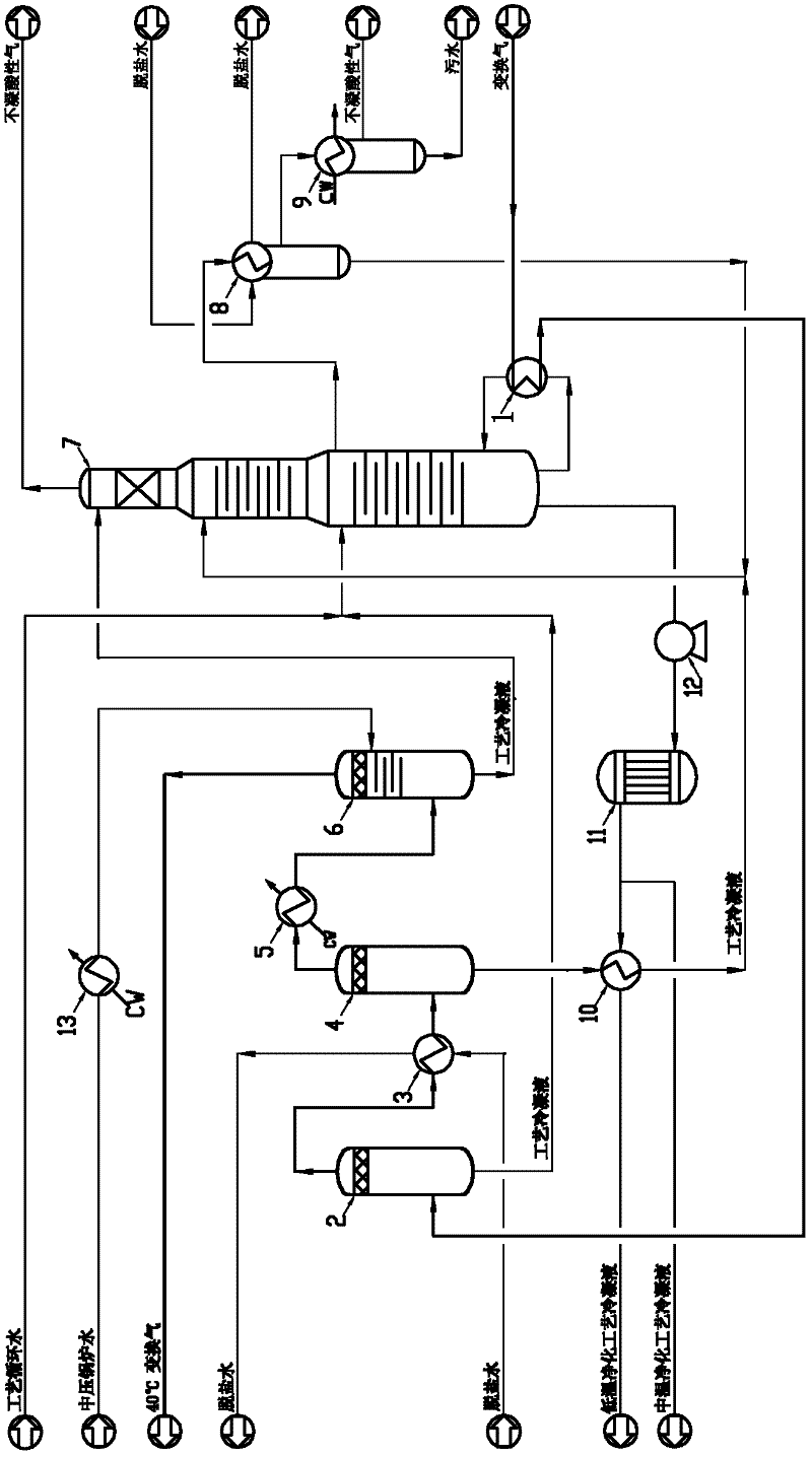
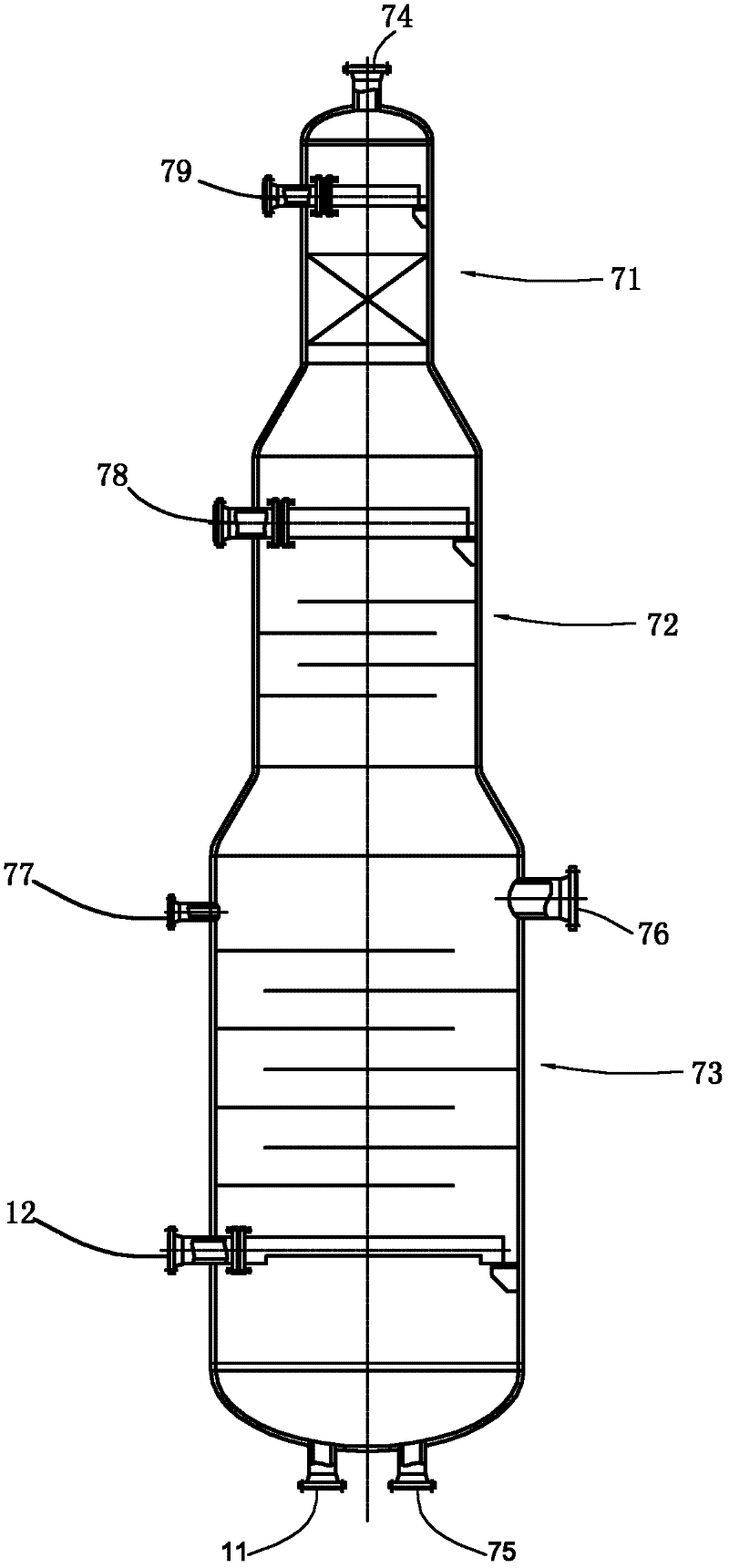
[0038] Such as figure 1 and figure 2 Shown, the structure of the used stripper 7 of embodiment is as follows:

[0039] The tower body of the stripping tower includes a lower section 73, a middle section 72, and an upper section 71 that are connected to each other and the tower diameters are successively reduced; wherein, the upper section 71 is a packed tower, and the upper section of the tower body is filled with fillers, and the height of the fillers is 2.0 meters; the middle section and the lower section It is a tray structure, and the number of theoretical trays is 4 and 5 respectively.

[0040] The bottom of the stripper is provided with a reboiler condensate outlet 11, and the bottom of the stripper is provided with a reboiler return port 12, and the stripper reboiler 1 provides heat to the stripper 7, and the The process condensate is stripped and separated; the top of the stripping tower is equipped with a CO 2 The first stripping gas outlet 74 for gas discharge, t...


PUM

PropertyMeasurementUnit
Heightaaaaaaaaaa

Abstract

The invention relates to a condensed fluid stripping method matched with a CO transforming device. The condensed fluid stripping method is characterized in that a stripping tower with an original structure is matched with a stripping process flow to carry out condensation three times and fluid distribution three times on transformation gas from the upstream; transformation-process condensed fluids are divided into multi-strand flows according to the difference of the temperature; the multi-strand flows enter the stripping tower from different parts; the function for reducing energy consumption of the stripping tower is fulfilled by scientifically and reasonably utilizing temperature potentials and energy gradients of different transformation-process condensed fluids; meanwhile, the transformation gas at 164 DEG C is used as a heat source for a reboiler of the stripping tower, and thus the energy consumption of a stripping system is remarkably reduced. Compared with the prior art, the condensed fluid stripping method disclosed by the invention has the advantages that the temperature of non-condensable acidic gas stripped by the stripping tower is 45DEG C; and a non-condensable acidic gas cooler at the top of the tower is canceled and no circular cooling water is consumed, so that the investment of equipment is saved and energy consumption is furthered reduced simultaneously. Due to the adoption of novel technologies such as single-tower stripping, cold-hot feeding and side-line ammonia extraction, the condensed fluid stripping method is simpler in control, more stable in operation and lower in energy consumption.

Description

technical field [0001] The invention relates to a CO conversion low-level waste heat recovery and condensate stripping method. Background technique [0002] The CO shift reaction refers to the process in which water vapor and CO react to form carbon dioxide and hydrogen, and it is an equimolar strong exothermic reaction. For the CO shift process using an adiabatic shift furnace, the high-temperature shift gas produced by the shift reaction can be used to produce medium-pressure steam through the waste heat boiler after leaving the shift furnace, or the high-temperature shift gas can be sprayed and quenched directly to increase the humidity and reduce the temperature of the shift gas. Purpose: After humidification and cooling, the shift gas re-enters the next adiabatic shift furnace to continue the shift reaction. [0003] It can be seen that it is easier to recover the high-temperature waste heat generated by the CO shift reaction between the shift furnaces, but when the sh...

Claims


Application Information

Patent Timeline
IPC IPC(8): C02F1/04C02F1/20
Inventor 许仁春施程亮邹杰陈莉卢新军徐洁唐永超
Owner CHINA PETROLEUM & CHEM CORP
Why Eureka
Try Eureka