Intermittent type waste rubber cracking device

A cracking device and old rubber technology, which is applied in the petroleum industry and the preparation of liquid hydrocarbon mixtures, etc., can solve the problems of ash powder scattering, time-consuming and laborious, and long time for slag removal, so as to achieve safety and environmental protection, improve the working environment, and further The effect of fast material speed

Active Publication Date: 2012-06-20
瑞新环境科技民权县有限公司
View PDF9 Cites 10 Cited by
  • Summary
  • Abstract
  • Description
  • Claims
  • Application Information

AI Technical Summary

Problems solved by technology

[0002] The production of fuel oil by pyrolysis of old rubber is an emerging industry to deal with black waste pollution in recent years. There are many types of pyrolysis equipment at home and abroad, and most of them have the problem of not being able to feed at high temperature, and the procedure for feeding at low temperature is also cumbersome. Unscrew more than 20 bolts on the furnace door to open the door, and the hydraulic feeder can be fed after the bolts are connected to the furnace door and tightened. After the feed is full, remove the bolts to separate the feeder from the furnace door. Then tighten all the bolts of the furnace door before production can be carried out. The work efficiency is low, time-consuming and labor-intensive.
[0003] The traditional equipment adopts the inner guide plate type slag discharge, and the ash and slag produced by each copying board is limited, and the slag discharge time is long, and the ash powder is scattered around when the slag is discharged, causing secondary pollution, and the working environment of the workers is poor.

Method used


Image

  • Intermittent type waste rubber cracking device
  • Intermittent type waste rubber cracking device

Examples


Embodiment Construction

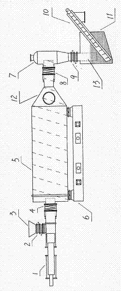
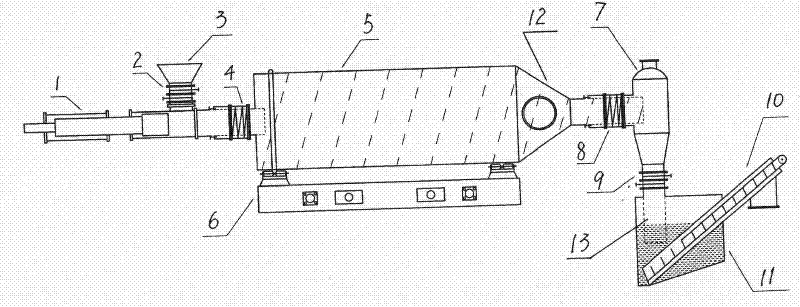
[0009] The invention as figure 1 As shown, it consists of a hydraulic feeder 1, a cracking kettle 5, an air slag separator 7, a combustion furnace 6, a slag discharge pool 11, and high-temperature gate valves 2 and 9. The hydraulic feeder 1 is connected to the On cracking still 5, there is a high-temperature gate valve 2 to be connected between the feed hopper 3 of hydraulic feeder 1 and hydraulic feeder 1; A dynamic and static sealer 8 is connected to the air slag separator 7; the pyrolysis kettle 5 is driven by the gear ring driven by the motor. Since the inner wall of the pyrolysis kettle 5 and the inner wall of the cone 12 at the discharge end are provided with spiral plates, the cracking kettle 5 will crack the gas while rotating. Waste slag is sent to the gas-slag separator 7; the slag outlet of the gas-slag separator 7 is connected to the slag outlet 13 through a high-temperature gate valve 9; the slag outlet of the gas-slag separator is set in the slag outlet pool 11 b...


PUM


Abstract

The invention provides an intermittent type waste rubber cracking device, which is composed of a hydraulic feeding machine, a cracking kettle, a gas-slag separator, a combustion furnace, a deslagging water tank and a high temperature cut-off valve, wherein the hydraulic feeding machine is connected with the cracking kettle through a dynamic and static sealer; one high temperature cut-off valve is connected between a feeding hopper of the hydraulic feeding machine and the hydraulic feeding machine; a cone is arranged at a discharge end of the cracking kettle with an inner screw; and a deslagging end of the gas-slag separator is connected with a deslagging opening through one high temperature cut-off valve. The deslagging opening of the gas-slag separator is arranged in the deslagging water tank below the gas-slag separator and the lower end of a scraper deslagging machine is arranged below the deslagging opening of the gas-slag separator. The intermittent type waste rubber cracking device provided by the invention has the advantages of fast feeding speed and short deslagging time; after materials are completely cracked, the continuous feeding and the continuous deslagging at a high-temperature state can be realized; a wet-type deslagging way is adopted, so that a phenomenon that ash residue flies off does not happen, the work environment is improved and the safety and environmental protection are realized.

Description

technical field [0001] The invention relates to an intermittent old rubber cracking device, in particular to a cracking device for continuous hydraulic feeding, intermittent cracking, and high-temperature slag discharge under high temperature conditions. Background technique [0002] The production of fuel oil by pyrolysis of old rubber is an emerging industry to deal with black waste pollution in recent years. There are many types of pyrolysis equipment at home and abroad, and most of them have the problem of not being able to feed at high temperature, and the procedure for feeding at low temperature is also cumbersome. Unscrew more than 20 bolts on the furnace door to open the door, and the hydraulic feeder can be fed after the bolts are connected to the furnace door and tightened. After the feed is full, remove the bolts to separate the feeder from the furnace door. Then all the bolts of the furnace door are tightened to produce, which is inefficient, time-consuming and l...

Claims


Application Information

Patent Timeline
Patent Type & Authority Applications(China)
IPC IPC(8): C10G1/10
Inventor 李昊民代先菊
Owner 瑞新环境科技民权县有限公司
Why Eureka
Try Eureka