
Device for reducing thrust and vibration at pipeline ends

An end thrust and pipeline technology, applied in the field of measurement and control, can solve the problems of easy vibration, high design and processing requirements, and reduced airflow quality, so as to meet the needs of thrust measurement, reduce pipe end thrust and coupled vibration. the effect of

Active Publication Date: 2012-06-20
中国航天科技集团公司第四研究院四0一所
View PDF5 Cites 16 Cited by
  • Summary
  • Abstract
  • Description
  • Claims
  • Application Information

AI Technical Summary

Problems solved by technology

The conditions of use are: the mutually butted pipes have thermal insensitivity in the axial direction, and the axial offset is small during the working process; this requires high design and processing technology, and it is difficult to achieve in practice, so The method is difficult to implement;
[0007] 3. The bellows displacement compensation method; using the deformation of the metal bellows expansion joint to absorb the displacement, although it can meet the displacement compensation requirements, it is easy to generate vibration, and it is difficult to realize the end of the thrust of the pipe end and eliminate the gas-solid coupling vibration of the system at the same time
The bellows reduces the quality of the airflow, and its compensation for displacement is at the cost of additional engine axial thrust, so it has a greater impact on engine ram combustion and thrust measurement; connecting metal bellows at the front end of the air intake can realize pipeline Thermal expansion displacement compensation, but due to the modulation of the corrugated surface, the quality of the airflow is degraded
[0008] 4. The sleeve compensator method; it has a good effect on the thermal deformation of the pipeline, but it needs to occupy a large space, and the compensation effect on the influence of the airflow blind plate force is insufficient;
[0009] The first two methods above have high requirements on materials and installation techniques, and are difficult to implement and apply in practice. The latter two methods are more commonly used pipeline compensation methods at home and abroad, but for a specific application such as thrust measurement , the existing treatment methods cannot meet the technical requirements, so a zero-stiffness compensation mechanism must be specially designed for dynamic thrust compensation, so the influence of various loads must be considered comprehensively, and a mechanism for reducing the thrust and vibration at the end of the pipeline must be provided

Method used


Image

  • Device for reducing thrust and vibration at pipeline ends
  • Device for reducing thrust and vibration at pipeline ends
  • Device for reducing thrust and vibration at pipeline ends

Examples


Embodiment

[0036] This embodiment is applied in the ramjet ground simulation test for measuring the thrust of the ramjet with high precision.

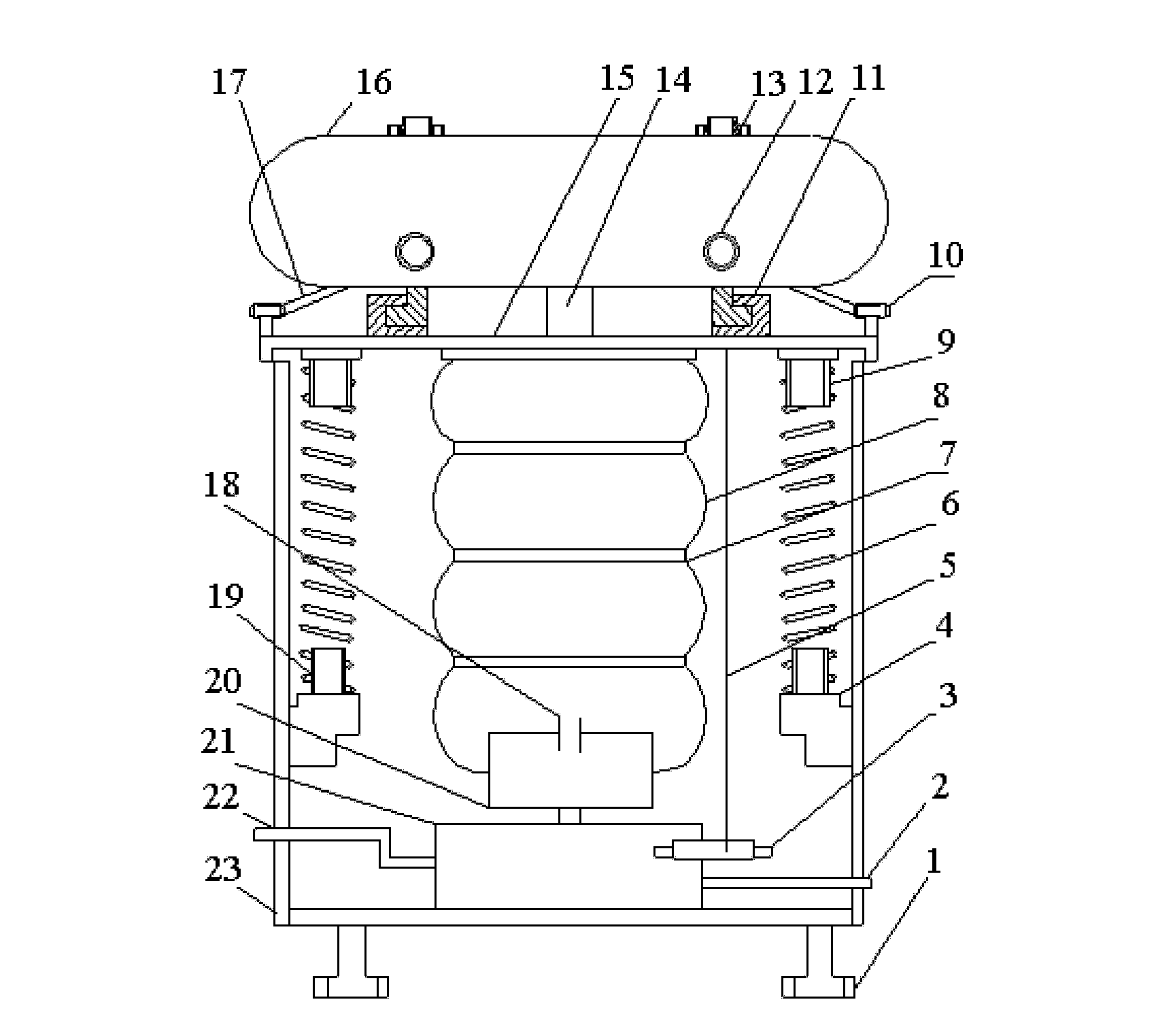
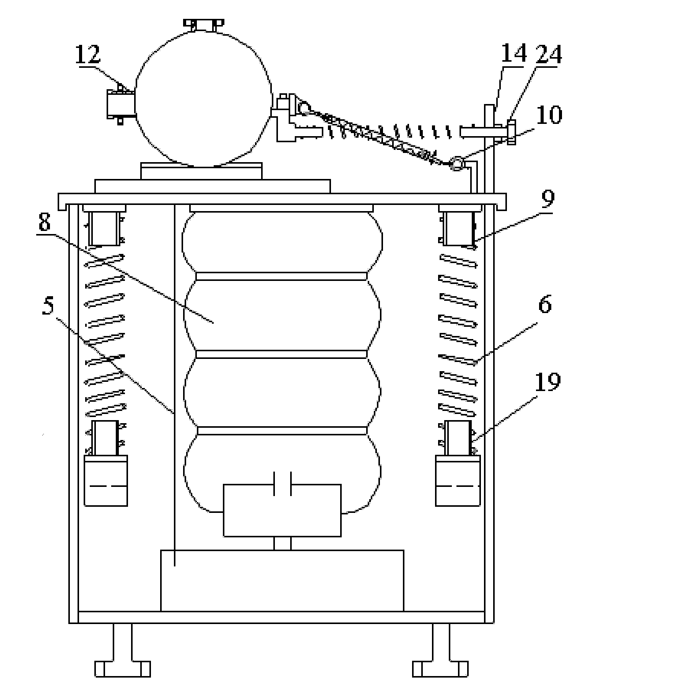
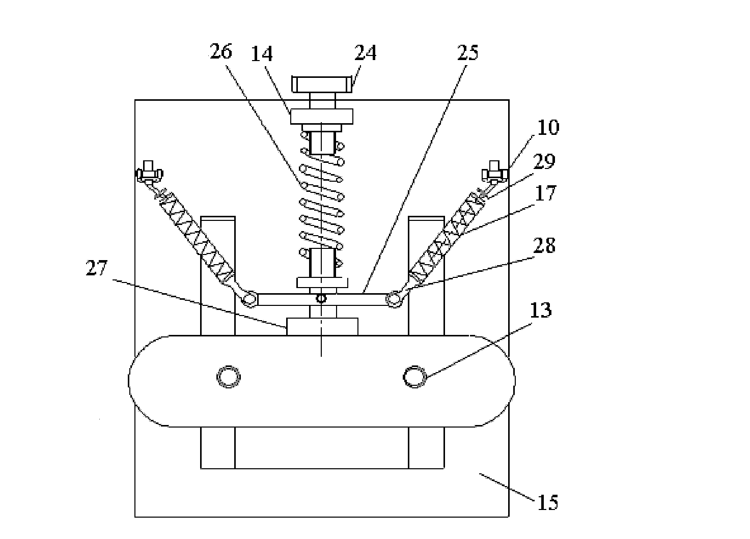
[0037] Refer to attached figure 1 A device for reducing the thrust and vibration at the end of the pipeline according to the present invention includes a movable buoy support assembly and a buffer cabin 16 .

[0038] Refer to attached figure 1 And attached figure 2 , the movable floating platform supporting assembly includes a load-bearing box 23, a movable platform 15, a supporting spring 6, an air spring and an air spring height control component. The load-bearing box is a square structure with an open end, and a connecting seat 4 is fixed on each of the four side walls of the load-bearing box, and the four connecting seats are located at the four corners of the load-bearing box. A connecting seat guide rod is fixed on the top.

[0039] The movable platform is placed at one end of the opening of the load-bearing box, and two slide grooves ...


PUM


Abstract

The invention provides a device for reducing thrust and vibration at pipeline ends, which comprises a movable floater supporting component and a buffer chamber. The movable floater supporting component supports a movable table through supporting springs and an air spring, the height of the air spring is controlled by an air spring height control component, the movable table is connected with the buffer chamber through a slide chute, and the buffer chamber is connected with an external vertical air inlet pipeline and an external engine inlet duct. According to the technical scheme, physical isolation of combined load affection between the air inlet duct and the external air inlet pipeline is realized. During operation, the movable table moves axially, the rigidity of the air inlet end of the pipeline on the movable table is close to zero, affection of the external air inlet pipeline to a measurement system is avoided, and the device can be suitable for sites having requirements for thrust measurement of testing targets such as the same type gas or liquid medium. According to the testing results, the device can evidently reduce affection of pipe end thrust and coupled vibration under composite load action and the requirement on thrust measurement can be met.

Description

technical field [0001] The invention relates to the technical field of measurement and control, in particular to a device for reducing thrust and vibration at the end of a pipeline. Background technique [0002] In the ground simulation test of the engine, the test object needs to be directly connected to the pipeline. Because the simulated intake air has the characteristics of high pressure, high temperature, and high speed, and because of the influence of pipeline, fluid and gas-solid coupling, the high-precision thrust measurement of the test object can be realized. It is relatively difficult, and the following technical problems need to be solved: 1) The interface between the thrust frame and the intake pipe is connected without thrust; 2) The change of the intake parameters of the system has no effect on the force measurement system, especially the dynamic characteristics of the interface; 3) Reduce Or eliminate the vibration caused by the pipeline to the measurement sy...

Claims


Application Information

Patent Timeline
IPC IPC(8): G01L5/00G01M15/02
Inventor 周东
Owner 中国航天科技集团公司第四研究院四0一所
Learn More