
Directional device of photoelectric tracker installed on naval gun bracket

A photoelectric tracker and azimuth technology, applied in the direction of control using feedback, can solve the problems of increasing the complexity of the structure, the volume and weight of the device, affecting the tracking accuracy of the servo control performance system, and requiring high axial dimensional accuracy, etc., to achieve improvement Mechanical properties and bending resistance, ensuring dynamic tracking accuracy, and the effect of no assembly stress

Active Publication Date: 2013-11-13
中国兵器工业第二0五研究所
View PDF5 Cites 0 Cited by
  • Summary
  • Abstract
  • Description
  • Claims
  • Application Information

AI Technical Summary

Problems solved by technology

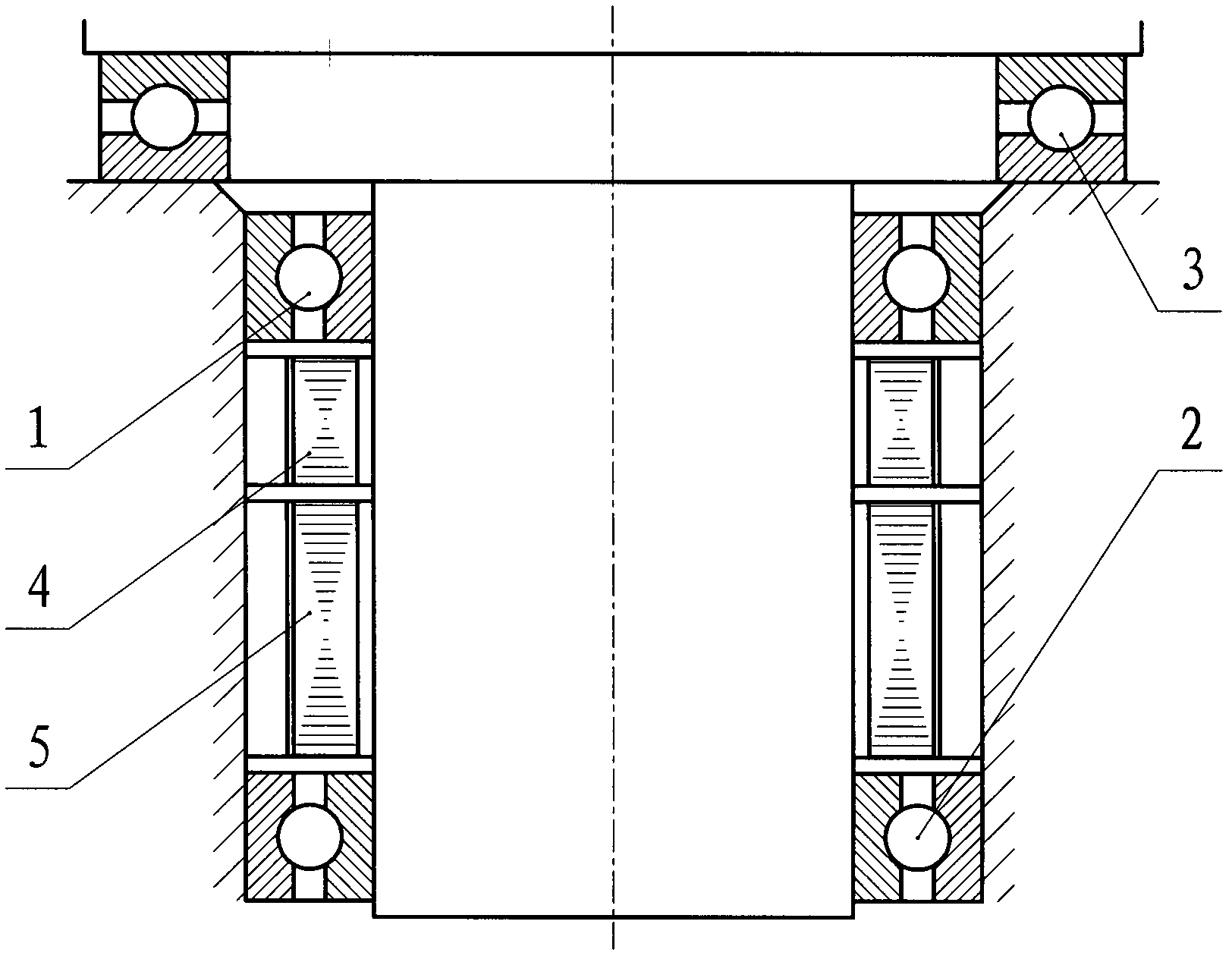
Due to the use of thrust bearings, this form has a greater load-carrying capacity, but also increases the complexity of the structure and the volume and weight of the device, so it is suitable for larger tracking turntables
In addition, this device also has the following deficiencies: (1) The requirements for the perpendicularity between the plane where the thrust bearing is installed and the azimuth main axis and the axial dimensional accuracy of related parts are relatively high, otherwise interference (or over-positioning) will occur, causing a large assembly (2) The friction torque of the thrust bearing is large and the centrifugal force of its rolling elements changes with the speed, resulting in a large range of friction torque, which affects the servo control performance and system tracking accuracy
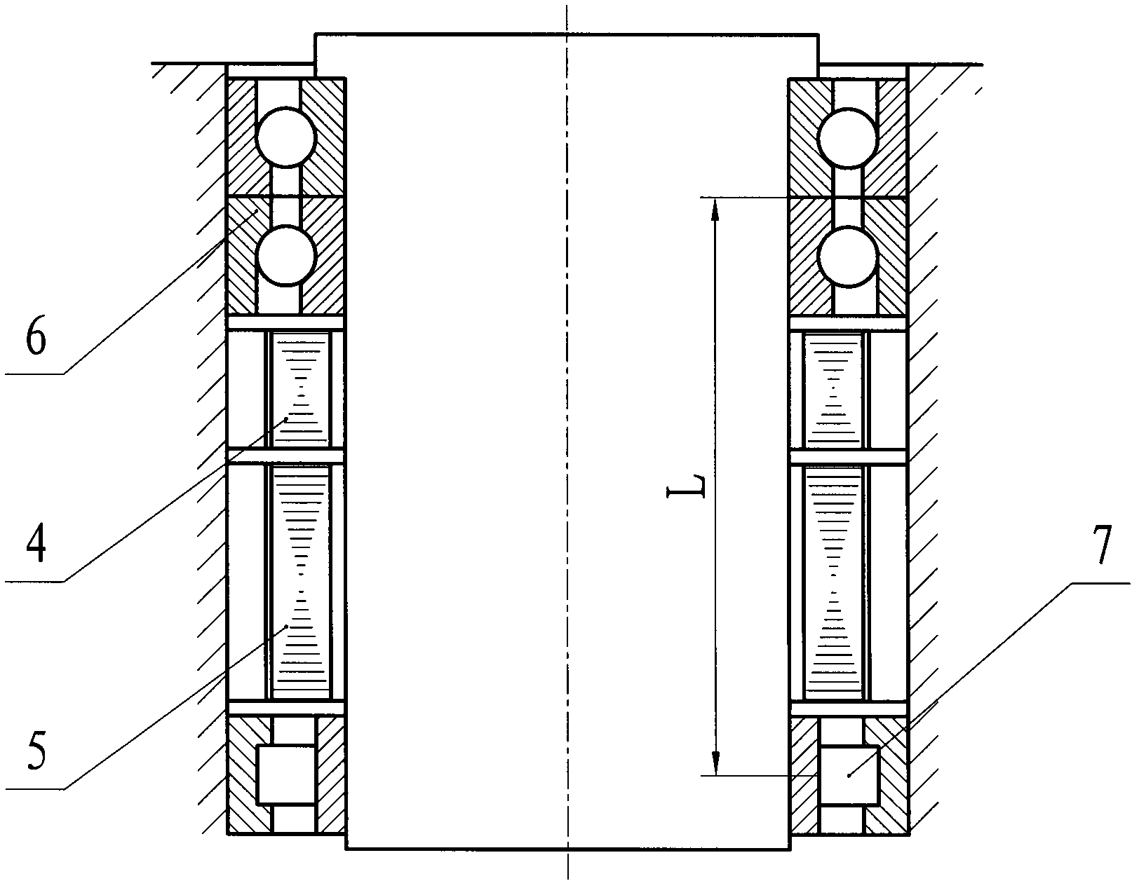
However, there are also some unfavorable factors: that is, in the case of using the same bearing, the influence of errors such as bearing sway on the accuracy of the azimuth device is inversely proportional to the bearing span L, and its stiffness is proportional to the bearing span L, so in order to improve Accuracy and rigidity, it is necessary to ensure that there is a long enough span between the bearings, resulting in an increase in the height of the device

Method used


Image

  • Directional device of photoelectric tracker installed on naval gun bracket
  • Directional device of photoelectric tracker installed on naval gun bracket
  • Directional device of photoelectric tracker installed on naval gun bracket

Examples


Embodiment Construction

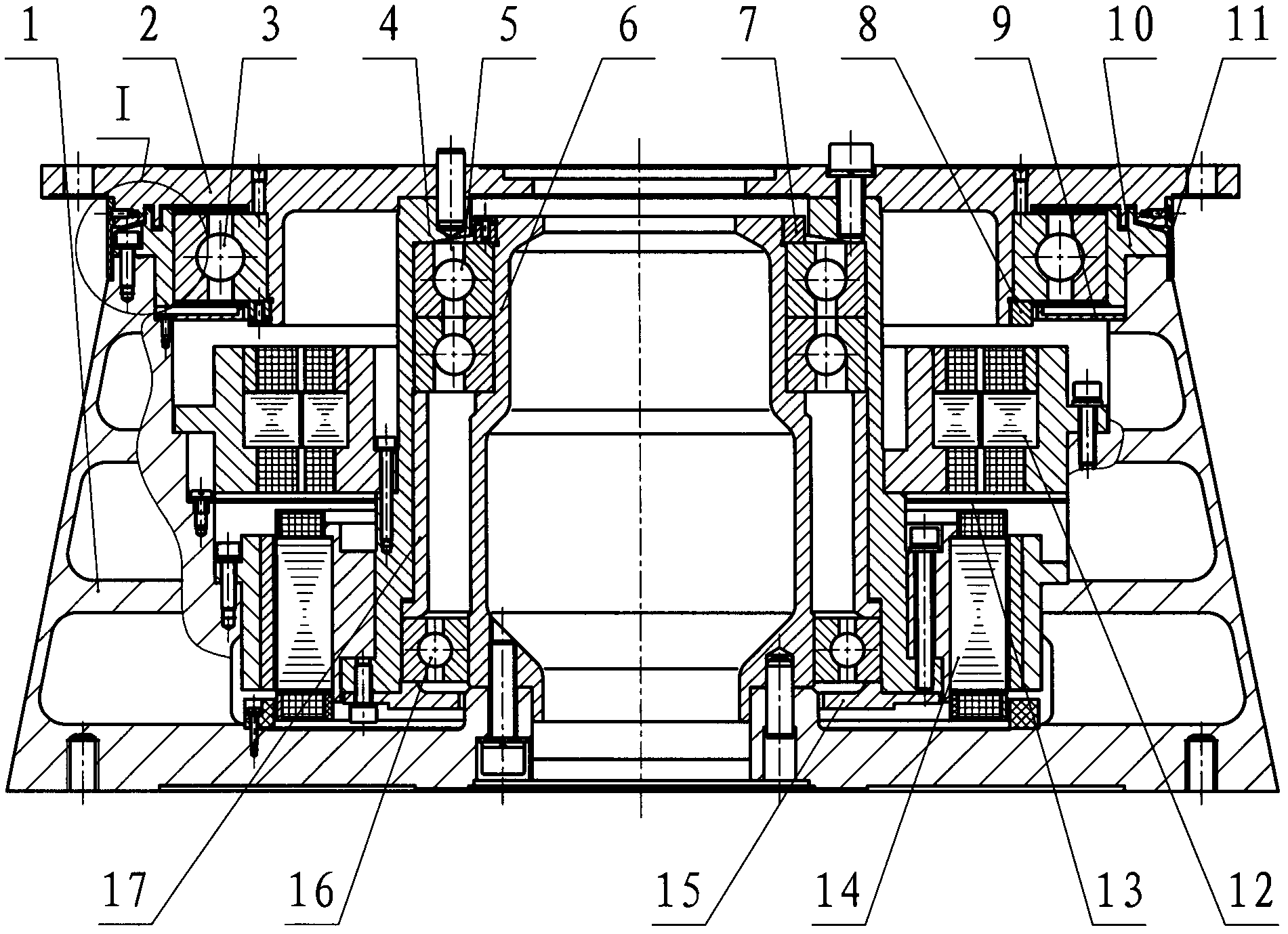
[0016] as image 3 As shown, the azimuth device provided by the preferred embodiment of the present invention includes a stationary part including an azimuth base 1, a bearing adapter seat 10 and an inner bearing seat 6, a rotating part including the azimuth coupling plate 2 and the azimuth shaft 4, and the space between the two A plurality of bearings, resolver 12 and torque motor 14 are connected. The azimuth base 1, the bearing adapter 10, the inner bearing seat 6, the azimuth connecting plate 2 and the azimuth shaft 4 all have a central through hole for installing a conductive slip ring or inserting a cable, so as to realize the direction of the load electrical signal at the upper end of the azimuth device. transmission at the bottom. For the stationary part, the inner bearing seat 6 is fixedly connected in the central through hole of the azimuth base 1 , the bearing adapter 10 is sleeved on the upper section of the inner bearing seat 6 with a large gap and the outer side...


PUM


Abstract

The invention discloses a directional device of a photoelectric tracker installed on a naval gun bracket. The directional device comprises a fixed part, a rotary part, a plurality of bearings, a torque motor and a rotary transformer, wherein the fixed part comprises a directional base, an inner bearing base and a bearing transfer base; the rotary part comprises a directional shaft and a directional connection disc; the plurality of bearings are connected between the fixed part and the rotary part; the inner bearing base and the directional shaft are connected through an angular contact ball bearing and a deep groove ball bearing; the inner bearing base is installed in the directional base; the directional connection disc and the bearing transfer base are respectively and fixedly connected at the upper ends of the directional shaft and the directional base; and an outer supporting bearing with larger outside diameter is arranged between the directional connection disc and the bearing transfer base. The directional device disclosed by the invention is not only capable of shortening axial size and increasing transverse support rigidity and bending resistance capability of the photoelectric tracker but also capable of improving the capability of resisting swing, inclination and transverse punching vibration of the photoelectric tracker; meanwhile, the directional device has the characteristics of simple structure, small volume, light weight, high reliability and good control property; furthermore, the directional device can be popularized and used for other similar tracking equipment with a plurality of carriers or installation positions.

Description

technical field [0001] The invention relates to a shipborne photoelectric tracker, in particular to a photoelectric tracker azimuth device installed on a naval gun bracket. Background technique [0002] The photoelectric tracker is a set of multi-band, multi-sensor, high-precision, high-automation comprehensive photoelectric equipment. detection and tracking, and complete the measurement of target motion parameters. For the photoelectric tracker installed on the naval gun bracket, its azimuth device is rigidly connected to the naval gun through the shell, and it is required that the volume and weight of the photoelectric tracker should be as small as possible, and the height of the center of gravity should not be too high. However, at the same time, the swaying and tilting of the ship and the violent shock vibration caused by the high-speed adjustment or firing of the naval gun, especially the lateral shock vibration, will directly act on the azimuth device of the photoelec...

Claims


Application Information

Patent Timeline
Patent Type & Authority Patents(China)
IPC IPC(8): G05D3/12
Inventor 马优恒陆培国王虎郭渝琳胡博崔海云
Owner 中国兵器工业第二0五研究所
Learn More