Short-circuit protection method for buffer output of DC/DC (Direct-Current/Direct-Current) power supply converter and buffer output circuit

A short-circuit protection circuit and snubber circuit technology, which is applied in the direction of output power conversion devices and electrical components, can solve the problems of loss of snubber circuit protection, increased drain-source internal resistance, increased voltage, and high short-circuit power consumption of power converters, etc. Problems, achieve the effect of reducing short-circuit power consumption, wide application fields, and low cost

Active Publication Date: 2012-06-20
MORNSUN GUANGZHOU SCI & TECH
View PDF4 Cites 8 Cited by
  • Summary
  • Abstract
  • Description
  • Claims
  • Application Information

AI Technical Summary

Problems solved by technology

[0004] When the load RL is short-circuited, the output voltage of the DC / DC module power supply drops, and the voltage divided by the first voltage dividing resistor R1 and the second voltage dividing resistor R2 and applied to the gate-source of the buffer MOS transistor T1 also drops rapidly. The buffer MOS transistor T1 exits the saturation region, the drain-source internal resistance of the buffer MOS transistor T1 increases and the voltage increases, and the short-circuit current of the converter is also very large at this time, which may burn out the buffer MOS transistor in severe cases
Therefore, this scheme of connecting the buffer circuit to the voltage output terminal of the DC / DC module power supply has a defect: in the case of a short-circuit of the load, due to the existence of the buffer circuit, the short-circuit protection function of the DC / DC module power supply will not work, resulting in Losing the protection of the snubber circuit, the snubber MOS tube in the snubber circuit is easy to burn out due to excessive short-circuit current, and at this time the short-circuit power consumption of the power converter is very large

Method used


Image

  • Short-circuit protection method for buffer output of DC/DC (Direct-Current/Direct-Current) power supply converter and buffer output circuit
  • Short-circuit protection method for buffer output of DC/DC (Direct-Current/Direct-Current) power supply converter and buffer output circuit
  • Short-circuit protection method for buffer output of DC/DC (Direct-Current/Direct-Current) power supply converter and buffer output circuit

Examples


Embodiment 1

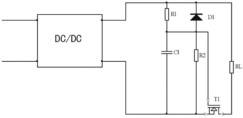
[0041] For the buffer circuit with output short-circuit protection in Embodiment 1, the parameter values ​​are as follows: DC / DC module power supply input voltage is 12V, the value of the first voltage dividing resistor R1 is 220Ω, the value of the second voltage dividing resistor R2 is 100KΩ, the first current limiting The value of resistor R3 is 300Ω, the second current-limiting resistor R4 is short-circuited, the buffer capacitor C1 and the delay capacitor C2 are both 1uf, the diode D1 is a diode of the type BAS16, and the buffer MOS tube T1 is an N-MOS tube of the type IRLR024. The first NPN transistor T2 is an NPN transistor 491 , and the second NPN transistor T3 is an NPN transistor 3904 . The measured threshold voltage Vgs(th) of the IRLR024MOS tube is actually 1.2V (the specification Vgs(th) is 1V-2V), and the trigger voltage of the short circuit protection circuit V1=Vbe(T2)+Vbe(T3)=0.6+ 0.6=1.2V. According to formula (1-1), take Vc=Vgs(th)=1.2V, VCC=Vo=5V, R=R1=220Ω...


PUM


Abstract

The invention discloses a short-circuit protection method for buffer output of a DC / DC (Direct-Current / Direct-Current) power supply converter and a buffer output circuit of the power supply converter, wherein a short-circuit protection circuit is arranged between the output end of a DC / DC module power supply and a buffer circuit; when a load is short-circuited, the short-circuit protection circuit is triggered to be in a short-circuit working state to cause that the output end of the DC / DC module power supply is short-circuited; then, short-circuit protection in the DC / DC module power supply is triggered, so that voltage output to the buffer circuit by the DC / DC module power supply is in a safe state, therefore, the short-circuit protection of the buffer circuit is realized; when the converter is started and the output load is normal, the short-circuit protection circuit is in an open-circuit working state; and, besides having load interference resistance capability, the DC / DC power supply converter disclosed by the invention is capable of realizing short-circuit protection of the whole DC / DC power supply converter when the load is short-circuited, preventing a buffer MOS (Metal Oxide Semiconductor) transistor in the buffer circuit from being damaged, and reducing short-circuit power consumption of the converter at the same time.

Description

technical field [0001] The invention relates to a short-circuit protection method, in particular to a short-circuit protection method for buffering output of a DC / DC power converter, and also relates to a buffer output circuit for realizing the short-circuit protection method. Background technique [0002] The basic structure of the traditional DC / DC module power supply application system is: the power supply system supplies power to the DC / DC module power supply, and the DC / DC module power supply supplies power to the load. The performance of the application system depends not only on the characteristics of the module itself, but also on the characteristics of its power supply system and back-end load. Due to the diversity and complexity of the use environment, different types of loads have different interferences on the power supply system. In severe cases, the system cannot work normally, or even permanently damage the system. However, customers have higher and higher re...

Claims


Application Information

Patent Timeline
IPC IPC(8): H02M1/34
Inventor 郭国文韦敏忠
Owner MORNSUN GUANGZHOU SCI & TECH
Why Eureka
Try Eureka