Natural gas hydrate generating device capable of being quickly disassembled for sampling
A technology for hydrate formation and natural gas, applied in the direction of chemical/physical/physicochemical fixed reactors, etc., to achieve the effects of low cost, simple disassembly, and delayed decomposition
- Summary
- Abstract
- Description
- Claims
- Application Information
AI Technical Summary
Problems solved by technology
Method used
Image

Examples
Embodiment Construction
[0028] The present invention will be further described below in conjunction with accompanying drawing:
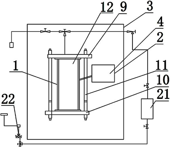
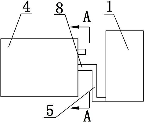
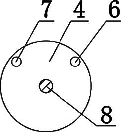
[0029] Such as figure 1 As shown, the gas hydrate generation device that can be quickly disassembled for sampling includes a reactor 1, a stirring device 2 and a DBR bellows 3, such as figure 2 , image 3 As shown, the stirring device 2 includes a reversible motor 4 and a fixed seat 5, the fixed seat 5 is installed on the motor shaft 8 of the reversible motor 4, and the reversible motor 4 is also provided with two limit switches, namely limit switch A6 And the limit switch B7; the reaction kettle 1 is installed on the fixed seat 5, and the stirring device 2 equipped with the reaction kettle 1 is arranged in the DBR bellows 3.
[0030] Such as Figure 4 As shown, the reaction kettle 1 includes an upper end cover 9, a lower end cover 10, a fixed assembly 11 and a plexiglass cylinder 12. An O-ring A13 is arranged between them, and the lower end cover 10 is installed on th...
PUM
 Abstract
Description
Claims
Application Information
 - R&D
- Intellectual Property
- Life Sciences
- Materials
- Tech Scout
- Unparalleled Data Quality
- Higher Quality Content
- 60% Fewer Hallucinations
Browse by: Latest US Patents, China's latest patents, Technical Efficacy Thesaurus, Application Domain, Technology Topic, Popular Technical Reports.
© 2025 PatSnap. All rights reserved.Legal|Privacy policy|Modern Slavery Act Transparency Statement|Sitemap|About US| Contact US: help@patsnap.com