
Multifunctional dehydrator

A dewatering machine, multifunctional technology for liquid/gas/vapor removal with centrifugal force, textile material drum processing, textile material processing equipment configuration, etc., can solve the loss of short fibers, poor quality flax fibers, no rinsing or dyeing function and other problems to achieve good quality results

Inactive Publication Date: 2012-06-27
WUXI QIANZHOU YAODA MACHINERY FACTORY
View PDF4 Cites 11 Cited by
  • Summary
  • Abstract
  • Description
  • Claims
  • Application Information

AI Technical Summary

Problems solved by technology

If the flax fibers are compacted in the cage like cotton fibers, the compacted flax loose fibers will form a huge "filter element". Although the solution can penetrate into the flax fibers during rinsing, the flax fiber The impurities in the fiber are relatively high, and there is a "filter element", which makes it difficult to separate the impurities in the flax fiber. Therefore, the quality of the flax fiber processed by this loose fiber dyeing machine is poor
[0003] And because the inner and outer cylinders of this kind of loose fiber dyeing machine are both porous cylinders, and there is no shielding measure inside the outer cylinder, during the treatment process, a large number of short fibers will be discharged from the tumbler through the holes on the outer cylinder under the repeated washing of the liquid flow. resulting in a large loss of short fibers
[0004] The traditional dehydrator only has dehydration function, no rinsing or dyeing function, it can only be used for dehydrating loose fibers, and cannot be used for rinsing or dyeing loose fibers

Method used


Image

  • Multifunctional dehydrator
  • Multifunctional dehydrator
  • Multifunctional dehydrator

Examples


Embodiment Construction

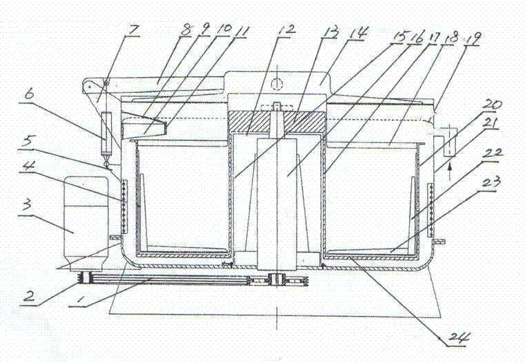
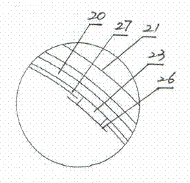
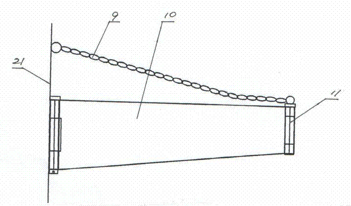
[0022] Such as figure 1 with figure 2 As shown, the multifunctional dehydrator of the present invention includes a cylinder body 21, the upper port portion of the cylinder body 21 is provided with a cylinder cover 14, and the cylinder cover 14 is provided with an activation arm 8, and the activation arm is fixed on the radial direction of the cylinder cover 14. The top of the cylinder cover 14. An upper pin seat 7 and a lower pin seat 5 are installed on the top of the outer surface of the cylinder wall of the cylinder body 21 and in the middle of the vertical direction, and the upper pin seat 7 and the extended end of the starting arm 8 are hinged together so that the cylinder cover 14 can be wound around the hinge. The pin shaft rotates, so that the opening and closing of the cylinder cover 14. A cylinder 6 is arranged between the lower pin seat 5 and the starting arm 8 , one end of the cylinder 6 is hinged on the lower pin seat 5 , and the other end is hinged on the inner...


PUM


Abstract

The invention relates to a multifunctional dehydrator, which comprises a cylinder. A cylinder cover is arranged at an upper opening of the cylinder. The bottom of the cylinder is provided with a center hole, and a spindle is arranged in the center hole. The lower end of the spindle extends out of the bottom of the cylinder, a power mechanism is arranged outside the cylinder, and the lower end of the spindle is connected with an output shaft of the power mechanism through a pulley and a transmission belt. A rotary cage is arranged in the cylinder, and a space is reserved between an inner cylinder of the rotary cage and the spindle while another space is reserved between an outer cylinder and the cylinder. A support board is connected to the upper end of the inner cylinder, and the upper end of the spindle is connected with the support board. An annular cage cover is arranged at the upper end of the rotary cage and is a meshed cage cover. The multifunctional dehydrator is characterized in that a sleeve for water proofing and heat insulation is arranged in the inner cylinder, and the lower end of the sleeve is hermetically connected with the bottom of the cylinder. A heater is arranged between the cylinder wall of the cylinder and the outer cylinder of the rotary cage. The dehydrator is multifunctional and used for treating linen fibers, quality of linen fiber products can be improved, and high loss of short staples is avoided. The multifunctional dehydrator is applicable to boiling, bleaching, washing and dehydrating of the linen fibers.

Description

technical field [0001] The invention relates to a dyeing and finishing equipment. Specifically, it is a multifunctional dehydrator for scouring, bleaching, washing and dehydrating flax fibers. Background technique [0002] At present, in the dyeing and finishing industry, traditional bulk fiber dyeing machines are still used for rinsing or dyeing flax fibers. This traditional loose fiber dyeing machine contains a cylinder and a circulation pump. A central rod is arranged in the cylinder, and a cage for holding the dyed fiber is fixed on the central rod. A base is fixed at the lower end of the central rod, and liquid inlets and outlets are processed on the base, wherein the liquid inlet communicates with the outlet of the circulating pump, and the liquid outlet communicates with the inlet of the circulating pump. The cage contains an inner cylinder and an outer cylinder, both of which are porous cylinders. A cage bottom is connected between the bottoms of the inner and out...

Claims


Application Information

Patent Timeline
IPC IPC(8): D06B5/14D06B15/10D06B23/02D06B23/22
Inventor 余耀平王涵君余育强蒋荣芯
Owner WUXI QIANZHOU YAODA MACHINERY FACTORY
Learn More