Driving wheel variable-speed gear

A technology of speed change device and driving wheel, which is applied in the direction of transmission device, gear transmission device, transmission device parts, etc., to achieve the effect of unique structure, low speed increase torque and speed change range, and wide application

Active Publication Date: 2012-06-27
山东济清科技服务有限公司
View PDF6 Cites 4 Cited by
  • Summary
  • Abstract
  • Description
  • Claims
  • Application Information

AI Technical Summary

Problems solved by technology

[0003] In order to solve the problem that some machines require high speed, wide speed range and high torque output at low speed, the present invention provides a moving wheel transmission device, which is equipped with a movable wheel train. When the movable wheel train moves outward, When the two pairs of gears are disengaged, the clutch is combined with the input shaft, the power input from the input shaft is transmitted to the output shaft through the clutch, and the power is output by the output shaft. At this time, there is no gear meshing and no gear noise; When the two pairs of gears are engaged, the clutch is disengaged from the input shaft, and the power input from the input shaft is transmitted to the output shaft after being decelerated by two stages of gears, and the power is output by the output shaft, thus achieving high speed and low noise , low-speed torque increase and the purpose of expanding the speed range

Method used


Image

  • Driving wheel variable-speed gear
  • Driving wheel variable-speed gear
  • Driving wheel variable-speed gear

Examples


Embodiment Construction

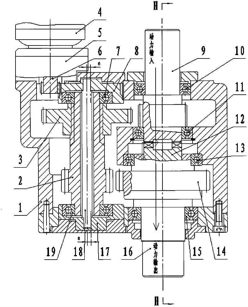
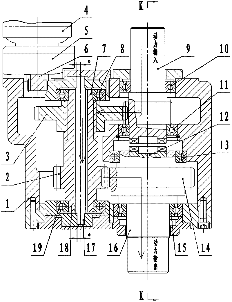
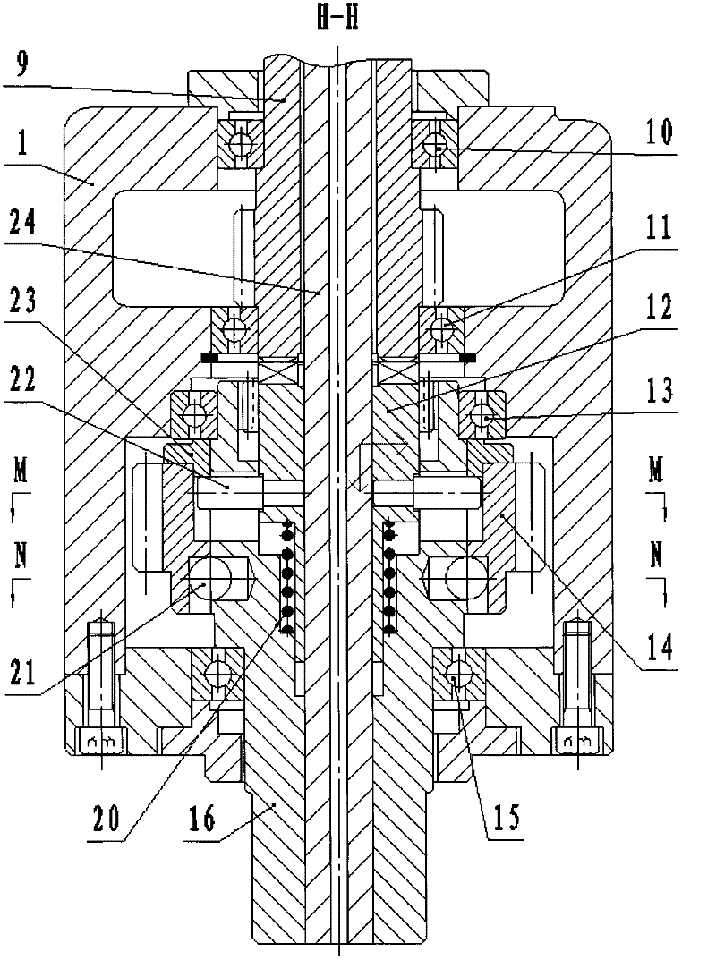
[0019] Such as figure 1 , 2 As shown, the moving wheel transmission includes a case 1, a gear shaft 2, a gear 3, a bearing 7, an input shaft 9, a bearing 10, a bearing 11, a clutch 12, a bearing 13, a gear 14, a bearing 15, an output shaft 16, and a bearing 19. Its characteristic is that the input shaft 9 is mounted on the case 1 through the bearing 10 and the bearing 11. The inner end of the input shaft 9 is provided with gears and end teeth, and the outer end of the input shaft 9 is connected to the power input device; the clutch 12 is mounted on the output On the shaft 16, the gear 14 is also mounted on the output shaft 16. The output shaft 16 is mounted on the housing 1 through the bearing 13 and the bearing 15. The outer end of the output shaft 16 is connected to the power output device, and the input shaft 9 and the output shaft 16 are coaxial ; The gear 3 is fixed on the gear shaft 2, the gear shaft 2 and the gear 3 constitute a coaxial gear train, and the coaxial gear tr...


PUM


Abstract

The invention discloses a driving wheel variable-speed gear, which is provided with a movable gear train capable of radially moving, and has two sections of rotating speed output when being matched with a variable-speed motor. When the movable gear train moves outward to disengage two gear wheels, the power input through an input shaft is directly output from a clutch and an output shaft, then gear wheel engagement and gear wheel noise are avoided; and when the movable gear train moves inward to engage the two gear wheels, the clutch is disengaged from the input shaft, the power input through the input shaft is transmitted to the output shaft after the speed reduction of the two gear wheels, and is output through the output shaft, as a result, the driving wheel variable-speed gear achieves the purposes of high speed and low noise, low speed torque increasing and speed range widening, has an unique structure, and is widely applicable.

Description

Technical field [0001] The invention relates to the field of mechanical speed change, in particular to a moving wheel type speed change device. Background technique [0002] With the rapid development of speed control systems such as switched reluctance speed control, frequency conversion speed control and servo speed control, some traditional mechanical speed change devices have been phased out. Switched reluctance speed control, frequency conversion speed control and servo speed control have been gradually eliminated. The system, through the control of the speed regulating motor, can make the motor output high speed, wide speed range and larger active power, which basically meets the power requirements of most mechanical equipment. However, since the existing speed control motors all have the weakness of constant torque output at low speeds, for machines that require high speed, wide speed range, and large torque output at low speeds, the speed control motor alone There is not...

Claims


Application Information

Patent Timeline
Patent Type & Authority Applications(China)
IPC IPC(8): F16H3/34F16H57/023F16H55/17
Inventor 党金行
Owner 山东济清科技服务有限公司
Why Eureka
Try Eureka