Parallel-flow heat exchanger and fabrication method thereof

A technology of parallel flow heat exchangers and headers, applied in the direction of refrigerators, refrigeration components, refrigeration and liquefaction, etc., can solve the problems of low waste rate of heat exchangers, difficulty in fixing, etc., achieve less leakage, wide application range, Flexible effects

Active Publication Date: 2012-06-27
MIDEA GRP CO LTD
View PDF6 Cites 11 Cited by
  • Summary
  • Abstract
  • Description
  • Claims
  • Application Information

AI Technical Summary

Problems solved by technology

[0005] However, since the flow equalizer is a long strip structure, and the inner cavity of the collector is a circular arc surface or similar arc surface, it is difficult to fix the two. When there is a cavity between the walls, it will give a large upward thrust to the flow divider. Therefore, there needs to be a strong connection between the flow divider and the inner wall of the collector, and it is often hoped that the flow divider and the inner cavity of the collector are tightly connected. The fixed connection between the two should not have refrigerant leakage on the contact surface. Only by ensuring the quality of this tight connection can the heat exchanger with the equalizer plate have a lower scrap rate, so that it is possible to carry out mass production.

Method used


Image

  • Parallel-flow heat exchanger and fabrication method thereof
  • Parallel-flow heat exchanger and fabrication method thereof
  • Parallel-flow heat exchanger and fabrication method thereof

Examples


Embodiment 1

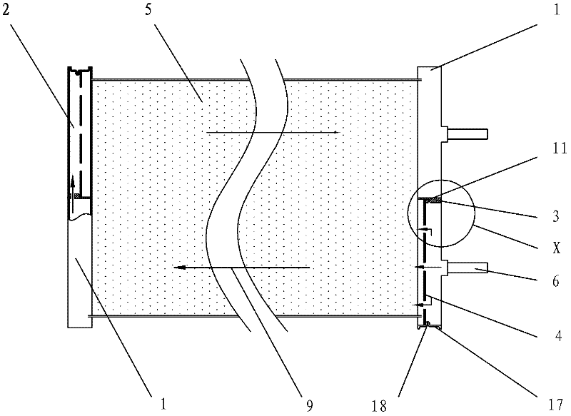
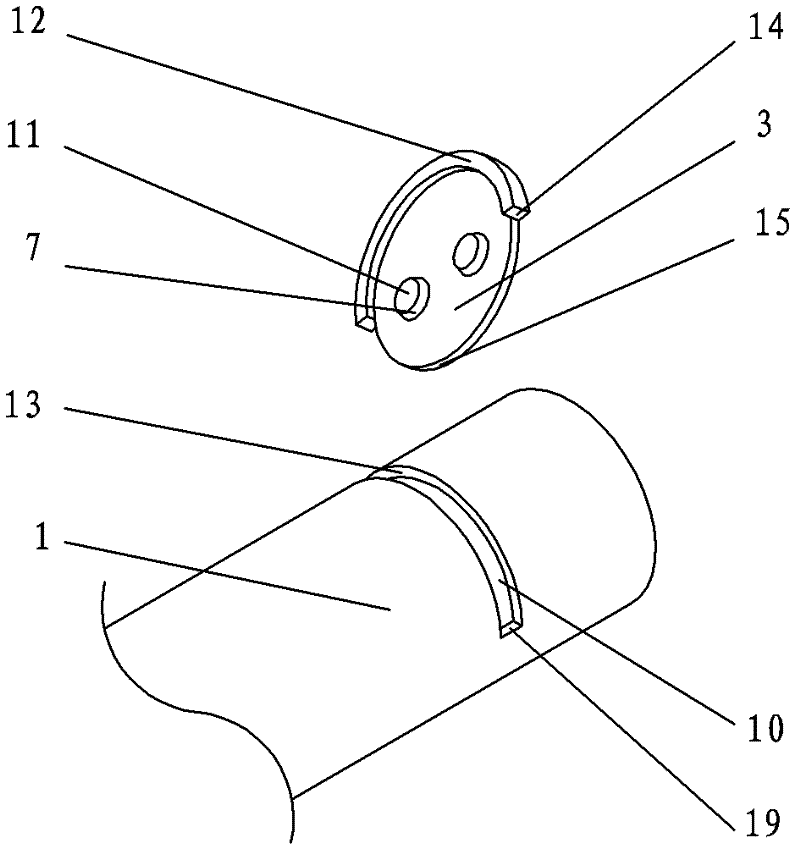
[0054] see Figure 1-Figure 6, this embodiment is a parallel flow heat exchanger with headers arranged vertically. The refrigerant enters the header 1 from the refrigerant pipe 6 below the right side. The inner wall of the flow tube 1 encloses the partition 2 of the collector. After the refrigerant passes through the flow equalizer 4 with the flow uniformity hole 21 set in the partition 2, it enters the flat tube 5 according to the direction of the process 9, and is collected to In the partition 2 located on the opposite side of the header 1 , the fixed partition 3 divides the cavities on both sides into disconnected, that is, the cavities on both sides become the partition 2 respectively. At this time, it is a disconnected partition.

[0055] In the present invention, process 9 refers to the header flowing from one side of the parallel flow heat exchanger through the flat tube to the other side of the header; specifically, it can be from the partition of a header through the...

Embodiment 2

[0074] see Figure 7 , The main difference between this embodiment and Embodiment 1 is that in this embodiment, H=18mm, α=45 degrees, L=33mm, M=15mm; M+H=15+18=33≤L=33 is established .

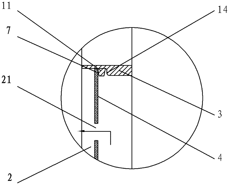
[0075] The end face of the flow sharing plate 4 pressed by the first crimping surface 7 of the fixed partition 3 is not a plane, but a positioning depression 20 is arranged on the end surface of the flow sharing plate 4, the shape of the positioning depression 20 is consistent with the first crimping The shapes of the surfaces 7 match each other, so that the contact area of ​​the first crimping surface can be further enlarged, the stability after welding can be improved, and the leakage of the contact surface can be reduced.

[0076] See Embodiment 1 for the rest of the undescribed parts, and will not repeat.

Embodiment 3

[0078] see Figure 8 , the main difference between this embodiment and Embodiment 1 is that in this embodiment, H=3mm, α=1 degree, L=6mm, M=3mm; M+H=3+3=6≤L=6 is established .

[0079] The cross-section of the crimping protrusion 11 of the fixed partition 3 is a rectangle, and the bottom surface of the rectangle is a crimping surface, so the crimping protrusion 11 cooperates with the end surface of the planar structure of the flow equalizer 4, and there will be a relatively large pressure. Joint area, and the stability after welding is significantly improved.

[0080] See Embodiment 1 for the rest of the undescribed parts, and will not repeat.


PUM

PropertyMeasurementUnit
Thicknessaaaaaaaaaa
Thicknessaaaaaaaaaa

Abstract

The invention relates to a parallel-flow heat exchanger and a fabrication method thereof. The parallel-flow heat exchanger comprises collecting pipes, a plurality of flat pipes arranged between the collecting pipes, and fins arranged between adjacent flat pipes. One end of a refrigerant pipe is connected with the collecting pipes in which flow equalization boards provided with flow equalization holes are arranged; a clapboard fixing groove is arranged on the collecting pipes; a fixed clapboard passes through the clapboard fixing groove; and a first crimping face of the fixed clapboard is crimped on the flow equalization boards. The clapboard fixing groove comprises a side wall and a stopping face; the fixed clapboard comprises a clapboard main body; a sealing lug boss matching with the surfaces of the collecting pipes is arranged on the clapboard main body; the sealing lug boss is in tight contact with the side wall and the stopping face; and the thickness L of the sealing lug boss is equal to the width of the clapboard fixing groove. The fixed clapboard further comprises a clapboard inner side which matches with the inner walls of the collecting pipes. The parallel-flow heat exchanger is simple and reasonable in structure, flexible in operation, low in fabrication cost, firm in connection, small in gap, little in leakage, good in stability and board in application range.

Description

technical field [0001] The invention relates to a parallel flow heat exchanger, in particular to a parallel flow heat exchanger and a manufacturing method thereof. Background technique [0002] As a high-efficiency heat exchanger, the parallel flow heat exchanger is used in more and more fields. However, in ordinary parallel flow heat exchangers, after the heat exchange medium enters the header from the refrigerant connection pipe, the refrigerant flows unevenly. When the refrigerant flow rate is large, the refrigerant will flow to the far end of the header, thereby A situation where the refrigerant is unevenly distributed in each flat tube occurs. [0003] In the prior art, a flow equalizing plate with a through hole is installed in the collecting pipe, and the refrigerant enters from one side of the flow equalizing plate, and flows into the other side of the flow equalizing plate after passing through the through hole, so that better flow equalization can be obtained. Ef...

Claims


Application Information

Patent Timeline
IPC IPC(8): F25B39/00
Inventor 刘阳李强
Owner MIDEA GRP CO LTD
Why Eureka
Try Eureka