
Laser projection display system

A display system and laser projection technology, applied in the field of digital light processing, can solve problems such as the disadvantage of laser projectors, the development and production of projectors that cannot complete the laser light source, and the limitation of the application of laser light sources, so as to achieve convenient and easy promotion and reduce dependence. the effect of reducing system cost

Inactive Publication Date: 2012-06-27
SICHUAN CHANGHONG ELECTRIC CO LTD
View PDF4 Cites 25 Cited by
  • Summary
  • Abstract
  • Description
  • Claims
  • Application Information

AI Technical Summary

Problems solved by technology

For the sake of commercial interests, these companies will not open the control technology for laser light sources to the public, which also limits the application of laser light sources by various manufacturers, making it impossible for manufacturers not authorized by them to complete the laser light source. Research and development and production of projectors, which is not good for the development of laser projectors

Method used


Image

  • Laser projection display system
  • Laser projection display system
  • Laser projection display system

Examples


Embodiment

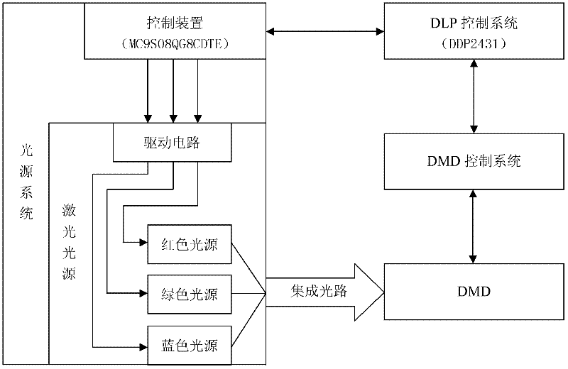
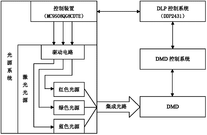
[0023] The laser projection display system in this example includes DLP control system, DMD control system, DMD and light source system. The light source system is composed of laser light source and its control device. See figure 1 . In the figure, the DLP control system is used to process the video signal and control the light source system, and project the light emitted by the light source system onto the DMD. According to the video signal output by the DLP control system, the DMD control system drives the DMD to modulate the light emitted by the light source system, and reflects it to the screen to synthesize an image. The laser light source in this example is composed of three primary color light sources: red, yellow, and blue, which can respectively emit corresponding primary color light. The control device of the laser light source in this example is composed of a single-chip microcomputer modeled as MC9S08QG8CDTE. The control device is connected to the DLP control syst...


PUM


Abstract

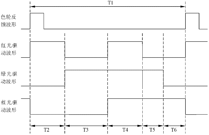
The invention relates to a DMD (Digital Micromirror Device) projection display system. The invention discloses the DMD projection display system adopting laser sources. A control chip of the DMD projection display system can use an ordinary commercial microprocessor, and special chips of Texas instruments and the like are not needed, so that the monopoly is broken. The laser projection display system adopts at least three laser sources containing three primary colors, the laser sources are controlled by a DLP (Digital Light Processing) control system, each monochromatic source is lightened, light shot on the DMD is light which has different colors and generated by a color wheel rotating, and the light is reflected by the DMD to synthesize a projection image. The control mode can utilize a PWM (Pulse Width Modulation) port of a laser source control device MCU (Microprogrammed Control Unit) to generate a color wheel feedback waveform in a simulative mode, only the waveform and the simulative color wheel synchronously rotate, and the laser projection display system can obtain a correct image like the traditional UHP (Ultra High Pressure) light-source projection system.

Description

technical field [0001] The present invention relates to digital light processing (DLP) technology, in particular to DMD (Digital Micromirror Device) projection display system. Background technique [0002] DLP is the abbreviation of "Digital Light Processing", that is, digital light processing, which means that this technology first digitizes the image signal, and then projects the light. It is based on the DMD developed by TI (Texas Instruments) to complete the technology of visual digital information display. To be more specific, DLP projection technology uses digital micromirror elements as the main key processing elements to realize digital optical processing. The principle is to homogenize the light emitted by the light source first, and then divide the light into three colors of R (red), G (green), and B (blue) through a color wheel (Color Wheel), or R, G, B, W (white) and other more colors, and then project the light of various colors on the DMD chip through the len...

Claims


Application Information

Patent Timeline
IPC IPC(8): G03B21/20G03B21/14H04N9/31
Inventor 李海青鲍雷华
Owner SICHUAN CHANGHONG ELECTRIC CO LTD
Learn More