Fiber grating measuring system of vehicle running speeds and positions

A technology of vehicle speed and fiber grating, which is applied in the traffic control system of road vehicles, traffic control systems, instruments, etc., can solve the problem of zero, and achieve the effect of improving durability, sensitive monitoring, and high precision

Inactive Publication Date: 2012-06-27
HARBIN INST OF TECH
View PDF4 Cites 6 Cited by
  • Summary
  • Abstract
  • Description
  • Claims
  • Application Information

AI Technical Summary

Problems solved by technology

However, in the field of transportation, practical applications such as the use of fiber grating sensors to measure the speed and position of vehicles are almost zero.

Method used


Image

  • Fiber grating measuring system of vehicle running speeds and positions
  • Fiber grating measuring system of vehicle running speeds and positions
  • Fiber grating measuring system of vehicle running speeds and positions

Examples


Embodiment 1

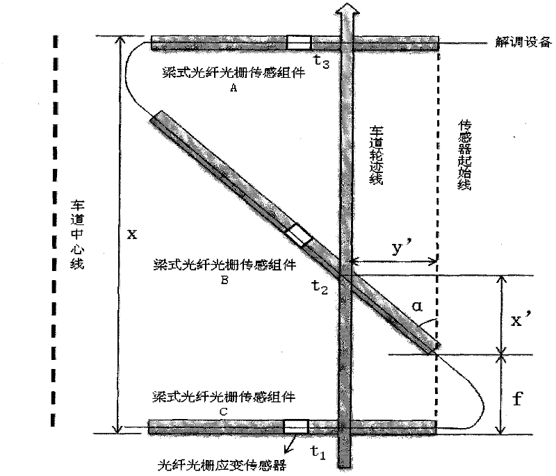
[0010] Example 1: Combining figure 1 , figure 2 , the present invention is a vehicle speed and position fiber grating measuring system, which includes three groups of beam fiber grating sensing components buried under the asphalt concrete or cement road surface, characterized in that: the beam fiber grating sensing component A and The beam fiber grating sensing component C is arranged in parallel, the beam fiber Bragg grating sensing component B is arranged between the beam fiber Bragg grating sensing component A and the beam fiber Bragg grating sensing component C, and the beam fiber Bragg grating sensing component B is oblique The orientation arrangement forms an α angle with the starting line of the sensor, and the α angle is 30° to 60°, and three groups of beam fiber grating sensing components are connected in series.

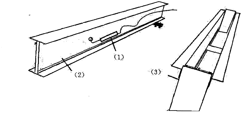
[0011] The present invention also has the following technical features: the beam-type fiber grating sensing assembly is composed of a fiber grating strai...

Embodiment 2

[0012] Example 2: Combining figure 1 , figure 2 , the principle of the vehicle driving position and speed measurement system, combined with figure 1 , the calculation process is as follows:

[0013] v = x t 2 - t 1 - - - ( 1 )

[0014] v = f + x ′ t 2 - t 1 - - - ( 2 )

[0015] x ′ = x t ...

Embodiment 3

[0030] Example 3: Binding figure 1 , figure 2 , the beam fiber grating sensing component A and the beam fiber grating sensing component C are arranged in parallel, the beam fiber grating sensing component B is arranged obliquely to form an angle of α degree with the starting line of the sensor, and connected in series Three sets of beam fiber grating sensing components. When the vehicle passes through the test system, the I-shaped steel beam will be bent and deformed by the gravity of the vehicle, and longitudinal tensile strain will be generated in the lower part of the beam, which is received by the fiber grating strain sensor and transmitted to the demodulator The equipment will generate a waveform diagram and correspond to the corresponding time t1, t2, t3. According to the above formula, calculate the speed of the vehicle and the value of y' from the formula (1) and formula (5), that is, determine the driving position of the car. Bury the beam-type fiber grating sensin...


PUM


Abstract

The invention discloses a fiber grating measuring system of vehicle running speeds and positions, and the fiber grating measuring system comprises three groups of beam type fiber grating sensing components, wherein a beam type fiber grating sensing component A and a beam type fiber grating sensing component C are distributed in parallel; a beam type fiber grating sensing component B is arranged between the beam type fiber grating sensing component A and the beam type fiber grating sensing component C and forms an angle of 30 DEG to 60 DEG with a sensor start line; each beam type fiber grating sensing component comprises a fiber grating strain sensor, an I-shaped steel beam and a steel tank; the fiber grating strain sensor is struck to one side surface of a web plate of the I-shaped steel beam; and the I-shaped steel beam is arranged at the inner part of the steel tank. The fiber grating measuring system has the characteristics that the structure form is simple, information is convenient to collect, the use is convenient by utilizing the fiber grating strain sensor, and the durability is good and the precision is high, and the fiber grating measuring system is used to measure the running speeds and the positions of vehicles on a bituminous concrete or cement pavement.

Description

(1) Technical field [0001] The invention relates to sensor measurement and detection technology, in particular to a vehicle speed and position fiber grating measurement system. (2) Background technology [0002] Since Morey et al. in the United States first researched the strain and temperature sensor of fiber grating in 1989, all countries in the world have paid great attention to it and carried out extensive application research. In just over 20 years, fiber grating has become the sensor field The fastest growing technology and has been successfully applied in many fields, such as aerospace, civil engineering, composite materials, petrochemical and other fields. The sensors involved mainly include fiber grating strain sensors, temperature sensors, acceleration sensors, displacement sensors, pressure sensors, etc. However, in the field of transportation, practical applications such as the use of fiber grating sensors to measure the speed and position of vehicles are almost...

Claims


Application Information

Patent Timeline
Patent Type & Authority Applications(China)
IPC IPC(8): G08G1/052
Inventor 王川张亮泉卢麒羽欧进萍
Owner HARBIN INST OF TECH
Why Eureka
Try Eureka